Frequently Asked Questions
Optical Lenses
In most cases, yes. Aspheres are typically designed so that the aspheric surface faces the object, or a collimated light source. This helps to spread the refraction, or bending, of light between the two surfaces of the lens and minimize spherical aberration. However, Best Form Aspheric Lenses are designed in the opposite configuration, so that a planar surface faces the object or collimated incident light. These types of lenses are simpler to design and achieve diffraction-limited focused spots on-axis for a given wavelength, but changing wavelengths result in chromatic aberrations and reduced performance for wavelengths different than the design wavelength.
Also, back reflections of light incident on the planar surface of best form aspheres bounce back directly towards the light source. This can be a cause for concern in many laser applications, making best form aspheres unsuited for some laser systems.
Edmund Optics offers a full line of mounting components that can be used to integrate the optics that you have chosen into your system. We carry components that can be used as stand alone units or they can be used together to create compound optical systems. We also carry various types of Mounting Components, including fixed, gimbal, and kinematic.
As a general rule of thumb, smaller lens f/#’s make it more likely that these issues will be a concern. If your application requires aspheric lenses and is sensitive to shifts in spectral performance, contact us to discuss these concerns and receive guidance on specifying the best lenses for your system. Learn more in our recorded webinar about Solving the Steep Challenges of Coating Aspheres.
Higher total sag, or saggita, heights of aspheres corresponds with more complexity. If the f/# of your lens remains constant, larger diameter lenses will have a greater sag and will therefore take longer to coat and be more susceptible to AOI and deposition effects.
This depends on the optical power of the lens. Aspheres with low optical power and aspheric departure can still achieve high diameters without experiencing these effects significantly. However, higher optical power aspheres may have steeper surfaces and high diameters result in high departures, and therefore greater AOI and deposition effects during coating.
The computer numerically controlled (CNC) polishing equipment used to fabricate the optics must have a large enough range of motion to properly polish the full asphere, and the weight of the lens may also become an issue when increasing its size. Large aspheres can also be more difficult to measure, especially if the saggital height is large enough that it prevents the stylus of a tactile profilometer from tracing the surface. Using a larger stylus to get around this issue may reduce measurement accuracy. Learn more about these considerations and the other steps Edmund Optics takes to ensure the accuracy of large diameter aspheres like the TECHSPEC® 200mm Diameter Precision Aspheric Lenses in our Large Aspheres: Enabling High-Power Optical Systems application note.
To couple light from a source into a fiber, a Ball Lens or lens with a positive focal length can be used. If the light is collimated, the lens must have a f/# greater than or equal to 0.5/NA, where NA is the numerical aperture of the fiber. The f/# of the lens is equal to f/D where f is the lens focal length and D is the beam diameter, not the diameter of the lens. This insures that the cone of light entering the fiber is within the fiber's acceptance angle. It should be placed away from the fiber at a distance equal to the lens focal length. A ball lens placed in contact with the fiber can also help couple light into the light guide. Its NA must be less than or equal to the NA of the fiber. This insures that the light is effectively coupled into the light guide. If the source is not collimated, i.e. light emitting from another fiber with a similar numerical aperture, one ball lens can be used to first produce a more collimated output beam and then another identical ball lens can be used to couple that light into the other fiber. The ball lenses should be placed in near contact to maximize efficiency.
No, advances in subaperture polishing have allowed for the fabrication of aspheres with surface figure error down to λ/20 (0.25µm). However, MRF is still required for the highest-precision aspheres, such as those with λ/40 (0.125µm) figure error.
Each glass type has its own set of specific characteristics. We have selected the best glass types available to produce optimal results for each individual lens design. This is the most significant in the design of achromat lenses since they use two different glasses together to help reduce optical errors (aberrations). Different glasses also have different transmission ranges. For applications dealing with the UV spectrum, special glass types such as Fused Silica or Quartz need to be used. For the visible spectrum many glass types can be used such as N-BK7, B270 and others. Many of these same glass types are used in the near IR region of the spectrum, but their transmissions vary greatly. Finally, the glass types have an impact on manufacturing capabilities, which directly relate to cost. For more information on our different glass types, please view Optical Glass. Note that even though a glass may transmit a specific wavelength, if this wavelength is significantly different from the lens' design wavelength then a lens made of that glass can have noticeable performance changes, such as the resulting back focal length.
Aspheric lenses are used to reduce the number of lenses in a design, simplify assembly and minimize stray light, eliminate spherical aberration, and improve resolution and system performance. They correct for spherical and off-axis aberrations. A single aspheric lens offers the same amount of spherical aberration correction that two or more spherical lenses can accomplish. Aspheric lenses, by their very nature, are without the spherical aberration that is inherent in traditional plano-convex and double-convex spherical lenses. In addition to spherical aberration correction, aspheric lenses are very powerful in correcting off-axis/ field dependent aberrations such as field curvature, astigmatism, and distortion. Because of this, complicated ten element designs can be reduced to relatively simple four or five element designs.
There are three varieties of aspheric lenses, each with its own benefit. Precision glass molded aspheric lenses are ideal for volume production requirements because of rapid production of many lenses and low tooling upkeep costs; polished aspheric lenses are ideal for prototype or low volume requirements because of short lead time, minimal special tooling and setup; and aspherized hybrid lenses are ideal for multi-spectral applications because of correction for both spherical and chromatic aberrations.
Please watch our How an EO Aspheric Lens is Made video to learn about the entire manufacturing process of an asphere from curve generation, in-process metrology, computer numerical controlled (CNC) grinding, CNC polishing, magnetorheological finishing (MRF), centering, coating, to final inspection.
The effective focal length of a lens is the distance from the primary plane of the lens to the focal point, when focusing light that is coming from infinity. The primary plane is determined mathematically and is located at a point within the lens, therefore making it extremely difficult to work with its position for mounting purposes. The back focal length is the distance from the back of the lens to the focal point of the lens when focusing light from infinity. The back focal length is much easier to use when determining a mounting position for a lens. See the accompanying diagram below:
Generally speaking, the use of a Holographic Diffuser, Condenser Lens, and Plano-Convex (PCX) Lens would satisfy the application. The holographic diffuser (elliptical in this case) would take the filament and image it as an approximate circular blur at a particular distance from the diffuser (based on diffusing angle chosen). By placing a filament 1 focal length from the condenser lens, the resulting output will be approximately collimated. Short focal length lenses tend to work best for this type of application. The PCX lens would then be used to refocus the light a given distance (EFL of the PCX Lens) from the lens. The distance of the PCX lens from the condenser lens is arbitrary. You can pick and choose relative to the application.
For example, you could use a Condenser lens (EFL = 13mm) and PCX Lens (EFL = 100mm). Place the condenser lens 13mm from the filament, and place the diffuser between the filament and condenser lens. The spacing between the condenser and PCX lenses can be 87mm (arbitrary). Overall, the resulting filament to final focal position is 200mm. Using geometry and trigonometry, you can determine exactly where the PCX lens needs to be placed in order to produce a 20mm spot at a distance of 200mm from the filament.
The system you are trying to model is basically a Koehler Illumination setup. We have a great EO Tech Tool – Koehler Illumination - that helps you choose the best lens parameters from a few simple variables.
Most optics can be cleaned using the "drag method." If done properly, the solvent will evaporate uniformly without leaving streaks or spots. Exceptions to this method include gold-coated optics, gratings, ZnSe optics, and micro optics. For more detailed information on cleaning, view Cleaning Optics. We offer a vast array of cleaning products including tissues/wipes, solvents, compressed air, gloves, swabs, tweezers, etc.
A lens with a positive focal length can help reduce the divergence angle of an output beam from an optical fiber. The lens must have a f/# less than or equal to 0.5/NA, where NA is the numerical aperture of the fiber. The f/# of the lens is equal to f/D where f and D are the lens' respective focal length and diameter. This insures that the lens will capture the cone of light exiting the fiber. It should be placed away from the fiber at a distance equal to the lens' focal length. A Ball Lens placed in contact with the fiber can also reduce the divergence angle of the output beam.
Aspheric lenses are used to reduce the number of lenses in a design, simplify assembly and minimize stray light, eliminate spherical aberration, and improve resolution and system performance. They correct for spherical and off-axis aberrations. A single aspheric lens offers the same amount of spherical aberration correction that two or more spherical lenses can accomplish. Aspheric lenses, by their very nature, are without the spherical aberration that is inherent in traditional plano-convex and double-convex spherical lenses. In addition to spherical aberration correction, aspheric lenses are very powerful in correcting off-axis/ field dependent aberrations such as field curvature, astigmatism, and distortion. Because of this, complicated ten element designs can be reduced to relatively simple four or five element designs.
There are three varieties of aspheric lenses, each with its own benefit. Precision glass molded aspheric lenses are ideal for volume production requirements because of rapid production of many lenses and low tooling upkeep costs; polished aspheric lenses are ideal for prototype or low volume requirements because of short lead time, minimal special tooling and setup; and aspherized hybrid lenses are ideal for multi-spectral applications because of correction for both spherical and chromatic aberrations.

Figure 1: Plano-convex spherical lenses show spherical aberration. Rays from the center focus at a different location than rays exiting from the edges.

Figure 2: A single aspheric lens can correct for spherical aberration vastly reducing the focused spot size.
The Edmund Optics® catalog contains lenses whose focal lengths are at least equal to or greater than their diameters. The reason for this is that smaller focal lengths with small diameter lenses create a very curved surface with thin walls, which becomes difficult to manufacture within the specifications EO provides for our lenses, namely our TECHSPEC® lenses.
The principal plane is defined as the imaginary surface at which a lens appears to bend light rays. The focal length is the distance from the backward principal plane to the backward focal point. The principal point is the point where the principal plane hits the optical axis.
1/s´ = 1/f + 1/s
s´ is the distance from image to principal point backwards
s is the distance from object to first principal point
f is the focal length
Another helpful formula is the one for Distance to Vertex:
S x H = -r x d /[ (n-1) d + n (r2 - r1)]
S is the vertex plane
H is the principal plane
r is radius
d is thickness
n is refractive index of the glass substrate
Both of the above equations can be used for two lens or two element systems. Edmund Optics® also offers complete prescription information for our negative achromatic lenses. You can input the specifications we provide into a program such as Olive, or pull up our stock numbers in the Zemax lens catalog and model whatever system you require.
Reversing the orientation of a Plano-Convex (PCX) Lens, pointing the convex side toward the source rather than the plano side, will maintain the location of the principle planes but will vary the Back Focal Length (BFL). Effective Focal Length (EFL) is measured from the principle plane so it is unchanged. BFL is a mechanical measurement and purely arbitrary. In the case of a PCX Lens, Edmund Optics® specifies BFL as the distance from the convex side to where incident collimated light comes to a focal point; if the lens is reversed, then this distance is now measured from the plano side to where the incident light focuses.
Edge-blackened lenses, or inked lenses, minimize the stray light within an optical system. Stray light in imaging and electro-optical systems can scatter off the ground edges of the lens elements within that system. The scattered light increases the noise which severely limits a system’s ability to reproduce contrast. Coating the edges with a black paint or ink minimizes the scattered light, improving the signal to noise ratio. Many of our Broadband Anti-Reflection (BBAR) coated lenses have been made available as off-the-shelf products with blackened edges. Achromatic lenses are available Edge-Blackened as well as our Plano-Convex, Double-Convex, Plano-Concave and Double-Concave Lenses. For more information, view Edge-Blackened Optics.
For low-end laser devices where the beam quality and divergence angle are not as important, you can often get away with a single aspherical lens. But whenever circularization, divergence, and confocality are essential, cross cylinders are generally the most cost-effective option.
You can use a negative focal length lens (Negative Achromatic Lens, Plano-Concave Lens, or Double Concave Lens) in combination with a Ball Lens to increase the back focal length of the ball lens. The focal length of the negative lens would have to be smaller in absolute value than the positive focal length of the ball lens in order to extend the back focal length. Another method to increase back focal length is to simply use a ball lens with as small an index of refraction as you can find. Our N-BK7 ball lenses have the smallest index and generally the longest focal lengths of any of our ball lenses. View Understanding Ball Lenses for additional information and useful equations.
Yes, we do have a stock lens solution for this. Cylinder Lenses placed one in front of the other, at the right distances, will invert the vertical dimension while maintaining the orientation of the horizontal. By taking two positive cylinder lenses and separating them by the sum of their focal distances, you will achieve a system that inverts the image without reversing it. The downside is that the resultant image isn’t very sharp which is what one would expect from what is basically a really inexpensive, one-dimensional Keplerian telescope.
Another, much simpler option is to use a Dove Prism. Dove prisms are used in binocular and telescopic systems to invert images in exactly the way mentioned. It's a simple, one-piece solution to your problem. It requires no focusing and is not as expensive as two cylinder lenses; but it is much bulkier than two cylinder lenses and would have to be placed very close one’s eye in order to work.
Edmund Optics® TECHSPEC® Plastic Aspheric Lenses and TECHSPEC® Plastic Hybrid Aspheric Lenses are both manufactured utilizing Zeon Chemical’s Zeonex E48R material. Zeonex materials feature high transparency, low fluorescence, low birefringence, low water absorption, and high heat and chemical resistance, making it a superior material vs. other commonly available plastics. Zeonex is a Cylco Olefin Polymer (COP) material.
Plastic Materials Selection Guide | |||||
---|---|---|---|---|---|
Property | Glass | Zeonex E48R | PMMA | Polycarbonate | Polystyrene |
Transmission | Excellent | Excellent | Excellent | Good | Very Good |
Low Refractive Index | Excellent | Excellent | Excellent | Poor | Poor |
Birefringence | Excellent | Excellent | Excellent | Poor | Poor |
Water Absorption | Excellent | Excellent | Poor | Good | Excellent |
Impact Resistance | Poor | Good | Good | Excellent | Good |
Moldability | Fair | Excellent | Good | Excellent | Excellent |
Heat Resistance | Excellent | Good | Poor | Good | Poor |
Coating Adhesion | Excellent | Good | Fair | Fair | Fair |
Beam homogenization setups typically consist of a pair of square Microlens Arrays and a Plano-Convex (PCX) Lens. The homogenization plane FP is located at one focal length distance ƒFL behind the spherical lens FL. The first array LA1 divides the incident beam into multiple beamlets. The second array LA2, in combination with the spherical lens FL, acts as an array of objective lenses that superimpose the images of each of the beamlets onto the homogenization plane FP.
The dimensions of the beam in the homogenization plane are given by:
The divergence q (half angle) after the homogenization plane is given by:
Design Considerations

- Microlens Pitch: For standard laser beams, the overlay of 9-10 microlenses is usually sufficient to achieve a good flat top uniformity. Consequently, the beam diameter Ω constrains the maximum microlens pitch PLA1 ≤ Ω/3.
- Diffraction Effects: For small microlens apertures and a long focal length, the flat top profile might be distorted by Fresnel diffraction at the lens apertures. Thus for small laser beams, a beam expander and diffuser will typically provide better performance than using microlens arrays with a very small lens pitch.
- Crosstalk: The diameter of the individual beamlets at the second array LA2 must be smaller than the lens pitch to avoid an overfilling of the lens aperture and loss of light. For laser beams with a significant beam divergence, the diameter of the beamlets at the second microlens array scales with the beam divergence.
- Damage: For high-power laser beams, focusing into the material of the second microlens array or the spherical lens must be avoided. An additional diffuser might be used to properly fill the aperture of the second array.
- Divergence: The beam divergence is increased by the beam homogenizer.
A Bessel beam is a non-diffractive beam comprised of rings equal in power to one another. Although Bessel beams are only theoretically possible because they require an infinite amount of energy, the output of Plano-Convex (PCX) Axicon Lenses offer a good approximation by maintaining a high level of the non-diffractive Bessel beam properties.
The ring thickness (t) is easily defined by taking ½ of the beam diameter (db):
The diameter of the ring (dr) is defined using the length from lens output to image (L), the index of refraction of the lens material (n), and the angle a:
Achromatic Cylinder Lenses are ideal for applications requiring magnification in only one dimension where a thin line profile is essential. They offer several performance advantages versus traditional cylinder lenses, including superior reduction of spherical and chromatic aberration at the image plane. When used with a LED source, Achromatic Cylinder Lenses are ideal for line generation. Typical applications include line generation with LED illumination sources and superior focusing with LED-based scanning devices. The illustration below compares a focused line with an Achromatic Cylinder Lens and one with a standard plano-convex (PCX) cylinder lens.

Strictly speaking, there are optical designs which enable fiber coupling without first collimating the output of the diode laser, but all of these designs suffer from massive astigmatism which can significantly reduce the efficacy of the fiber coupling. Having a collimated beam inside of the laser package allows for the addition of optical elements such as micro-optical isolators and bandpass filters.
Any visible pits and scratches will create light scatter which would be insignificant if there is plenty of light available but would decrease the signal in a low-light level application. An optic with a 20-10 scratch-dig, for example, will have better surface quality than an optic with 60-40. Provided the thicknesses are the same, glass transmission for uncoated fused silica is similar to the transmission for uncoated float glass in the visible range of the spectrum. UV Fused silica, however, does have much better transmission in the UV compared to float glass, if you would like a window with a higher surface quality rating.
Unfortunately, that information is not available for these lenses. While we are able to provide zemax files for our TECHSPEC Molded Aspheric Condenser Lenses as well as our Molded Aspheric Condenser Lenses, the prescription data is simply not available on Condenser Lenses.
To integrate these lenses into your optical design, you may consider modeling the lens as a paraxial lens with the specified clear aperture and focal length. Note that these lenses should only be designed into non-imaging applications, such as illumination subsystems.
Yes, short ultrafast pulses interact with optical coatings and substrates in a way that is different from other laser pulses, leading to different damage mechanisms. For more information, please read our LIDT for Ultrafast Lasers application note.
EO utilizes a wide range of metrology to support our asphere manufacturing including Talysurf PGI 1240 profilometers, QED ASI aspheric stitching interferometers, Zygo® NewView white light interferometers, OptiPro UltraSurf 4X 100 non-contact profilometers, TRIOPTICS Opticentric® centering machines, Zeiss Contura G2 coordinate measuring machines (CMMs), Olympus MX51 microscopes, design-specific computer-generated holograms (CGHs), and null lenses.
Yes, magnetorheological finishing (MRF) is still required for the highest quality aspheres and can achieve accuracies exceeding λ/20.
There are many different types of aspheric lenses with their own advantages and disadvantages, as shown in the table below:
Asphere Type | Description | Relative Price |
Precision Aspherized Achromatic Lenses | Diffraction-limited and color-corrected doublet with aspheric surface for broadband applications | $$$$ |
“Laser-Grade” Aspheres | <λ/10 transmitted wavefront | $$$ |
Precision Polished Aspheres | Most common asphere type, offering a balance between cost and performance | $$ |
Best Form Aspheres | Modified PCX or PCV lenses with one aspheric surface | $$ |
Diamond Turned Aspheres | Made out of high end plastics and crystalline materials | $$ |
Hybrid Aspherized Achromatic Lenses | Low cost doublet with molded polymer diffractive surface to minimize chromatic aberration | $ |
Molded Aspheres | Low cost plastic or glass lenses suited for high volume production | $ |
Liquid lenses change focus to different working distances in a matter of miliseconds.
A Polarization Directed Lens is a thin (0.45mm) flat window with a complex photo-aligned liquid crystal polymer (LCP) film deposited on the surface. By varying the geometrical phase shift spatially, the LCP achieves near perfect diffraction efficiency of the holographically recorded lens wavefront. Essentially, a Polarization Directed lens is a thin film equivalent of a geometric optic with very little volume, yielding significant reductions in weight and thickness.
Polarization Directed Lenses are a thin film equivalent of a geometric optic. Thus, they have significantly less volume than an equivalent spherical optic, yielding significant reduction in weight and thickness. The technology used to create them is also well suited to create gratings and other polarization optics, allowing for multiple optical technologies to be designed into a single optical component.
To operate as efficiently as possible, the lenses require the incoming light to be circularly polarized. This requires extra care in the setup, and potentially additional polarization optics in the optical design. Also, the lenses function as a grating, and thus have significant chromatic aberration when used with broadband illumination. Care should be taken to limit the spectral bandwidth of the illumination for optimum results.
Polarization Directed Lenses can be cleaned with the same methods used for other anti-reflection coated optics. Visit our application note on Cleaning Optics for more information.
All of our standard Polarization Directed Lenses are 25 x 25mm. Our 25mm Square Rectangular Bar Clamp, #54-994, is a good choice for bench mounted applications.
Optical Mirrors
Edmund Optics offers mirrors with a variety of metallic mirror coatings. Each coating is optimized for a particular spectral region, so care must be used to select a coating that best meets the wavelength, durability, and cost demands of one's application. Protected Aluminum is our most popular mirror coating for applications in the visible and near-Infrared. Enhanced Aluminum is ideal for applications requiring increased reflectance from 400nm-650nm while UV Enhanced Aluminum yields increased reflectance from 250nm-400nm. Protected Gold is effective for applications requiring high reflectance in the near-Infrared and Infrared regions. Protected Silver offers excellent reflectivity in the visible and infrared regions, making it an excellent choice for broadband applications that span multiple spectra. For all these coatings, the theoretical reflectance rises gradually through 10μm.
These values refer to the surface accuracy specification for the polished substrate of a mirror. Surface Accuracy describes the maximum allowable deviation of an optical surface from a perfect surface. If the mirror were flat, the value would give a reference as to "how flat". Since the test method used for inspecting surface accuracy uses a specific wavelength, the value is defined in terms of this wavelength. All catalog values refer to a maximum peak-to-valley value at 632.8nm. For high accuracy parts, the amount of deviation is so small that the value is defined as a fraction of a wavelength of light. For example, a ¼-wave mirror has a surface accuracy of 158.2nm (0.25 x 632.8nm), which is equivalent to 6.2 micro inches. The lower the value of the fraction, the higher the accuracy. Typically only values less than ¼-wave are considered as precision and values less than 1/10-wave as high precision quality. As a comment on notation, the following values are equivalent: ¼-wave, ¼λ, and λ/4, where λ is the value of the test wavelength.
Mirrors are typically bonded to the aluminum mounting surface of a mirror mount with a two part adhesive. We carry Milbond Adhesive System, two part epoxy, which can be used for most glass-to-metal mirror bonding applications. This epoxy should be used for substrates that will not be subjected to very hostile environments.
A typical mirror is a flat glass substrate with a metallic reflective coating applied to one side. If the coating is applied to the top surface, it is called a first (or front) surface mirror. The other surface may be clear (during fabrication of the glass or by polishing) or ground and the mirror is oriented so that the coating faces the source. If the coating is applied to the bottom surface and overcoated with black paint, then it is called a second (or back) surface mirror. The other surface in this case must be clear and the mirror is oriented so that the glass is facing the source in order for the light to pass through the glass before reflecting off the coating. The black paint (not always used) is used to protect the coating from the other direction and prevent any minimal transmission. An example of a second surface mirror is a common bathroom mirror. A second surface mirror is usually not preferred over a first surface mirror in most applications due to many inherent characteristics. A second surface mirror suffers from lower reflectivity due to absorption by the glass (especially in the UV and IR). In addition, there are often ghost images due to two reflections (one from the glass, one from the coating) and an increased optical path length since light passes through the glass twice (once to reach the coating and once to reflect back). A second surface mirror does have the advantage of increased protection of the coating. If the coating is very delicate or the environment is harsh, a second surface mirror may be selected (typically with a thin glass substrate).
A majority (but not all) of our first-surface mirrors are shipped with a protective plastic coating (a type of Molar® film overcoat) that protects the reflective surface. If the second surface is not ground, it looks like a second surface mirror when it is viewed from that side, but actually it is the bottom of the first surface coating reflecting through the glass. The plastic coating makes the top of the first surface look slightly dull and typically bluish in color as the mirror is tilted. The protective plastic coating can be removed by using Scotch® Tape or non-marring tweezers. Refer to the diagram below or view our video Removing Protective Plastic Coating for more information.
Yes. If linearly polarized light is incident upon a mirror (whether aluminum or gold coated), the polarization is rotated 180° to the incident beam.
See our Optics Cleaning Application Note for mirror cleaning techniques. Gold-coated mirrors are more delicate than aluminum-coated mirrors and can be easily scratched when using the drag method. Non-contact cleaning, such as ultrasonic cleaning, is the preferred method of cleaning.
Unfortunately, our Off-Axis Parabolic Mirrors are not damage threshold tested. They are not intended for use with high power lasers.
Optical performance of the mirrors is limited by the maximum temperature at which 6061 Aluminum (the mirrors’ substrate) begins to stress-relieve. The surface figure may begin to change at this point. Damage to the coating may occur beyond 200° C, though we do not have tested data to validate this. In the case of our Aluminum coated Off-Axis Parabolic Mirrors, damage refers to oxidation and crystallization of the coating; whereas, for the Gold coated versions, damage refers to de-lamination of the coating from the substrate.
Our Off-Axis Parabolic Metal Mirrors are machined to a rough surface figure, and then finely polished by a machine to the surface specification we list. They are then coated via Ion-Assisted Electron Beam Deposition in a coating chamber to apply the metallic coating. The coating layer is extremely fine and does not affect the mirrors’ surface specifications.
When polarized light is incident on a conductive surface like a metallic coating, a 180° phase factor gets added to the beam. If you start with linear polarized light, this rotates the polarization direction from θ to θ +180° which is the same linear polarization direction. Circular polarization, which can be defined as two equal linear states with 90° phase difference between them, undergoes a more obvious change. 180° is added to the phase difference and it becomes 270° (or -90°). This means the linear state that was leading is now lagging the other (orthogonal) piece by a quarter wave.
The low AOI of ultrafast highly-dispersive mirrors allow for reflections between multiple mirrors, so several mirrors will be used at once for maximum dispersion compensation and pulse compression.
CRDS can only be used to measure mirrors with a reflectivity above 99.5% because lower reflectivities result in ring down times that are too fast for the system to detect. The best technique to determine reflectivity depends on the reflectivity level and application requirements.
Mirrors with reflectivities below 99.5% can be directly measured using reflection spectrophotometry. However, this technique will not work for mirrors with higher reflectivities because these systems reach the signal-to-noise ratio (SNR) limit.
The design parameters required to make a cost efficient, custom OAP include the reflected focal length, reflected angle, the tolerance for the focal point, and the reflected wavefront distortion.
Windows and Diffusers
MgF2 has the solubility of approximately 0.0002g per 100g water at room temperature. So if the water is moving, it means that the MgF2 will be continuously dissolving at a very slow rate. After a long period of time, the whole layer of coating may be totally removed. In addition, the detergent solution will be alkaline [depending on the detergent used, pH value will vary from 7.5 (dishwasher) to 12 (commercial grade detergent)], there is a possibility that the MgF2 will react to form a salt which will appear as a white stain on the coating. In summary, MgF2 would not be ideal for long term use under water. Even if you use an uncoated window, there could be some staining from the glass reacting with the detergent.
Ground glass is produced by taking clear float glass and sandblasting it with a grit. Grit refers to the size of the sand particle impacting on the glass. The process of sandblasting creates divots in the glass, which then diffuse any light that passes through it. Ground glass has the advantage of being able to control the relative amount of diffusion that occurs depending upon the grit of the sandblast. For example, a 220-grit ground glass will diffuse more than a 120-grit glass. On the other hand, opal glass is float glass where one side is flashed with a milky white coating called "opal". It is this opal coating that acts as a diffuser for light passing through the glass. While both will diffuse transmitted light, opal glass diffuses more efficiently but causes a significant amount of scattering loss. Also, due to the thickness specification of the coating, opal glass should not be used in highly-toleranced opto-mechanical systems. Ground glass is best used in projection systems as a screen.
Because of the technique used in the fabrication of opal diffusers, the opal coating layer is subject to some variations. While the typical opal layer is 0.45mm thick, the thickness of this layer can vary anywhere between -0.2 and +0.35, giving the opal layer a possible thickness between 0.25 and 0.8mm. Due to the limitations in the manufacturing process, it is not possible to get a tighter thickness tolerance. The variation in the coating tolerance then results in a variation of the total filter thickness.
Actually, opal and ground glass diffusers are excellent depolarizers. Light that is linearly or circularly polarized will become randomly polarized when scattered after passing through a diffuser. Please note that the same is not true for holographic diffusers. Holographic diffusers are made of a birefringent material and will act as a retarder in polarized light.
Holographic diffusers, a type of Holographic Optical Element (HOE), give a higher transmission of light than typical ground or opal glass diffusers. Because of their design, holographic diffusers also offer a more even distribution of light. They also give the added bonus of allowing the user to control the amount of diffusion by selecting the diffusion angle and aspect ratio. Holographic diffusers can increase transmission efficiency to greater than 90% from filament lamps, LEDs, arc lamps, and other sources. It is important to note that diffusing angles listed for these diffusers are for collimated light and angular divergence will vary for different incidence angles. Although they do offer better diffusion and control, they tend to be priced higher than typical ground or opal glass diffusers.
Two methods are acceptable when cleaning holographic diffusers. One way is to use a de-ionized water rinse followed by forced air drying. The other way is to soak a lens tissue with methanol and wipe the diffuser clean (using the "drag method"), followed by either forced air or nitrogen drying.
Edmund Optics® offers three types of diffusers. The major differences between them come down to distribution and transmission.
Distribution means the angular distribution of light as it leaves the surface of the diffuser. In other words, for each of the 180° that light can leave the surface, how much light travels in that direction. With Opal Diffusing Glass, each of the 180° gets about 1/180 of the light as it diffuses evenly in all directions. This is good for even distribution of light over a large area at a short distance. With Ground Glass Diffusers, more light goes straight through than out towards the edges which results in a bell curve shaped distribution; this is the ideal for most applications. Holographic Diffusers are specifically designed so that all the light leaves in a fairly even distribution at a specified angle. The advantage here is that by specifically designating the area of distribution, you can make the most of the light you have and not waste it at unwanted angles.
Transmission is a little more straightforward. Opal diffusing glass transmits about 30-40% of visible and NIR light. It does not transmit at all in the UV. This low transmission makes Opal diffusing glass the best choice only when you need its extremely wide and even distribution. Ground glass diffusers transmit about 40-50% of visible and NIR light and are available in UV fused silica which transmits about 40-50% of UV. The moderate transmission and distribution of ground glass diffusers make them the most popular choice for diffusers, as they are well suited for most applications. Holographic diffusers transmit greater than 85% of visible and NIR light and are also available in a UV version which transmits about 90% of UV, visible and NIR. This coupled with tightly controlled distribution make them the ideal choice for making the most of a small amount of light.
All diffusing angles are not created equally. Certain diffusing angles or range of diffusing angles for our Holographic Diffusers work better for particular applications compared to others. Use the following selection guide to determine which is right for you.
Holographic Diffuser Selection Guide | |
---|---|
Application Need | Recommended Diffusing Angle |
Reduce Speckle | 0.5°, 1°, 0.2° x 40° |
Minimize Glare | 5°, 10°, 15°, 5° x 30° |
General Lighting | 15°, 20°, 25°, 30°, 40°, 60°, 80°, 5° x 30°, 10° x 60° |
Short Distance Homogenizaion | 60°, 80° |
Display Screen | 60°, 80°, 1° x 60°, 10° x 60° |
Optical Filters
The first step is to determine what type of filter is required for the application. The basic types of filters are Color, Shortpass, Longpass, and Neutral Density. Each type of filter has unique characteristics that lend it to one application or another and each is defined in detail in our Technical Library's Glossary. The second step is to determine what wavelengths are of interest. filters are defined by what part of the spectrum they pass or do not pass. For instance, an UV Cutoff (or Longpass) filter is designed to pass both the visible and IR portions of the spectrum, but block (or "cut") the UV portions of the spectrum. See the example below for more information:
Example:
A common application for CCD cameras is to block off the near-IR (700 to 1000nm). Since most light sources emit light in the near-IR, a filter is required to pass only the visible spectrum (400 to 700nm). The type of filter that passes the visible and blocks the near-IR is a Shortpass (opposite of Longpass) filter. We offer IR Cutoff filters that satisfy this requirement.
That decision is based on your application, each type of material has its own pros and cons. We supply three major types of materials used for our filters: glass, optical cast plastic, and gelatin film. Glass filters are the most durable and generally have the best surface accuracy, but can be expensive and weight becomes a factor in an assembly. Optical cast plastic filters are lightweight and have excellent thermal and chemical resistance, but tend not to have as precise a surface accuracy and are also capable of less transmission than a glass filter. Gelatin Film filters are extremely lightweight, very thin (on the order of 0.1mm) and can be cut by ordinary scissors into any size or shape. However, they have less transmission than glass or plastic filters, need to be handled only by their edges, need care in mounting to ensure a flat surface, and can only be stored in temperatures below 50°C.
While there are different types of colored filters that will work for imaging applications, generally colored glass filters or films are the best choice. Dichroic color filters are not typically recommended for imaging use. The color separating that is done by dichroic filters is angularly dependent. As the angle of light coming into the filter increases from the filter's center, the colors that the dichroic filter transmits shifts from the design wavelengths. The effect is that light in the center of a red filter will pass through as red, but light at a large angle (i.e., at the edge of the filter) may pass through as orange or even yellow.
For filters in general, as the angle of incidence increases, a filter's transmission curve will shift to lower wavelengths. The effect of large angles from the center of the optical system is the same as tilting a filter from a perpendicular position to an optical system. As the angle of tilt gets larger, the curve will start to change shape, this typically means the transmission will steadily drop and the slopes in the curve will start to change. A similar effect is noticed as temperature increases. Interference filters are the most sensitive to angle of incidence and temperature.
The decision is usually based upon the application. An IR (infrared) cut filter will reflect the IR and pass the visible wavelengths. These filters can generally be made very thin due to the fact that the filtering effect is created by a thin film coating and not the glass. The main drawback is that they are angularly dependent. With heat absorbing glass, the near IR wavelengths are absorbed by the glass and cause the glass to increase in temperature. For this reason the filter needs to be thicker and a way to evacuate the heat is required. Due to the high potential for damaging the filters with excessive heat, we always recommend using plenty of air space, apply heat sinks, select tempered glass when available, and use forced air-cooling as required. We suggest for first time configurations to monitor the heat situation closely to avoid damage to any optics. If components get excessively hot over a short period of time, they will eventually crack.
An ND, or neutral density filter, is a type of filter designed to decrease the intensity of the input light without affecting the color (or spectral) distribution. Due to this neutral characteristic, the filters appear gray in color. ND filters are typically designated by their optical density (OD). Transmission for an ND filter can be calculated by using the equation T=10-OD x 100 = Percent transmission Where OD is the optical density of the ND filter. Typical applications for ND filters include decreasing light consistently over the visible or near infrared spectrum, protecting sensing devices from excessive intensity, such as blooming/overexposure of CCD cameras or testing the linearity of a photodetector or photodiode. ND filters are preferred over polarizers for reducing light in the case of extreme light intensities.
Yes, ND (neutral density) filters exhibit an additive relationship with their optical density values. For instance, stacking filters with Optical Density values of 0.6 and 0.9 yield a resultant optical density of 1.5 (which gives an overall transmission of 3%) Care should be taken when using the reflective type of ND filter in order to insure that the reflected light does not interfere with the application. In stacks, the reflective filters are not parallel in order to reduce back reflections.
There are two types of ND (neutral density) filters: absorptive and reflective. The absorptive type absorb light that is not transmitted, while the reflective type reflect it away. An absorptive ND filter has greatly reduced back reflections when compared to its reflective counterpart. This can be very important for various applications that are severely affected by back reflections, such as electronic imaging. However, since absorptive filters tend to absorb the light passing through them, the result is a slight increase in temperature. If critical temperature control is a factor in your application, we recommend using a reflective ND filter. Also, in absorptive ND filters, optical density is a function of glass thickness - the higher the optical density required, the thicker the filter will need to be. Reflective ND filters gain their properties through a coating material, allowing for thinner substrates and tighter thickness tolerances regardless of optical density. Care should be taken when using the reflective type of ND filter to insure that reflected light does not interfere with the application. In stacks, the reflective filters are not parallel in order to reduce back reflections.
Reflective ND (neutral density) filters and Interference filters will function as specified with either side facing the source. However, we recommend orienting the side with the "mirror-like" reflective coating toward the source. This will minimize any thermal effects resulting from the absorption of the heat by the glass on the other side. Also, having the "mirror-like" side facing away from the source will cause an interference pattern when the source is a coherent beam of light. For filters in general, the coated surface is oriented toward the source. In addition, filters will perform optimally if positioned in a collimated beam of light. This will reduce the angle of incidence and the performance results will closer match that of the filter's design. Interference filters in particular, are extremely sensitive to angle.
The coated surface is easily determined by looking at the edge of the substrate, from the direction of the center of the filter at a slight angle so looking at the inside edge. If you can see the actual edge (thickness) of the glass, then the coating is on the other side. From the coated side, the edge is not visible. This is more difficult to check on coatings that transmit in the visible, but the edge can still be detected by viewing the filter at a steep angle.
For a detailed information on cleaning, view Cleaning Optics. Please note that some filters are coated and others are filters due to the glass itself (homogeneous) and therefore the two require different types of cleaning techniques.
Thermoset CR-39 is relatively rigid and difficult to cut by standard methods i.e. using scissors. The rigidity of the substrate causes it to crack when proper care isn’t used. However, there are several cutting methods to employ, each with its own pro and con:
- High-Speed Carbide Drill – this is the most manageable method and great for making mounting holes but it is hard to cut lines or find a high speed router
- High-Speed Saw – this is easy and fairly accessible to many but has the highest probability of causing damage to the substrate if too much heat or vibration is generated
- Score and Break – this is the simplest of all methods where one scores the substrate with a sharp knife and snaps along the scored line; it is not exact at all since one has to depend on line of sight and if the score isn’t deep enough one can crack the entire sheet by trying to break off the excess bit
- CO2 Laser – this produces the best, most uniform results but it is also the most dangerous since extra precautions must be taken to ensure one’s safety
In Raman Spectroscopy, a clean excitation signal is a vital component in ensuring accurate measured scatter data. Our high performance bandpass and longpass filters complement each other very well in this regard. The high transmission and narrow bandwidth of the bandpass filters eliminates signal noise and ensures only the desired laser line reaches the sample. The high blocking and narrow transition of the laser line filter then eliminates the excitation signal and allows accurate measurement of wavelengths very close to the laser line.

A notch filter is designed to block a pre-selected wavelength region or bandwidth, while transmitting all other wavelengths within the design range of the filter. Different methods exist to design and manufacture notch filters, however, the two most common are the dielectric stack method and the Rugate method.
Dielectric Stack Method
Dielectric Stack notch filters are simple filters fabricated using a series of thin layers (discrete layers) of dielectric materials, of alternating refractive index. While relatively inexpensive to make, dielectric stack filters suffer from the presence of harmonic structure, which can severely limit the transmission band.
Rugate Method
Edmund Optics® offers both Dielectric Stack Notch Filters and Rugate Notch Filters. A Rugate notch filter is constructed using a single layer thin film in which the refractive index varies continuously with position in a direction perpendicular to the substrate plane. This design eliminates the harmonic structure problems of Dielectric Stack filters, yielding high transmission across a broad wavelength range. The wavelength range for transmission of the rugate notch filter is limited only by the materials used in its construction. In addition to offering a very broad transmission range free from harmonic structure, the rugate notch can provide deep blocking (high optical density) as well as a high degree of reflectivity at wavelengths within the notch.
The figure below shows the comparative transmission spectrum for a notch filter made with a Rugate design and a notch filter made with a simple, non-optimized Dielectric Stack design. The largely harmonic-free transmission band associated with the Rugate design provides high out-of-band transmission over a very broad range of wavelength. Rugate notch filters are used for many laser-based applications including medical/surgical, spectroscopy, laser-based fluorescence, astronomy, and in display applications.

Yes, Edmund Optics® offers a line of Ultra-Thin Longpass Filters, Ultra-Thin Shortpass Filters, and Ultra-Thin Notch Filters made from ultra-thin polymer layers. They are scratch insensitive and have thicknesses ranging from 200-500µm.
Common filter substrate materials include fused silica, N-BK7, and float glasses. Recently a trend towards fluoride materials, IR crystalline materials like silicon and germanium, and polymers and plastics has emerged.
The first step is to determine what type of filter is required for the application. The basic types of filters are shortpass, longpass, bandpass, dichroic, notch, and neutral density. Each type of filter has unique characteristics that lend better to one application or another. The second step is to determine what wavelengths are required, as filters are defined by what part of the spectrum they pass or do not pass. For instance, an UV Cut-Off (or Longpass) filter is designed to pass both the visible and IR portions of the spectrum, but block (or "cut") the UV portions of the spectrum.
Generally, as the angle of incidence increases a filter's transmission curve will shift to lower wavelengths. The effect of large angles from the center of the optical system is the same as tilting a filter from a perpendicular position to an optical system. As the angle of tilt gets larger, the curve will start to change shape, causing the transmission to steadily drop and the transmission curve slope to change. A similar effect is noticed as temperature increases. Interference filters are the most sensitive to angle of incidence and temperature.
Ultra-Thin Filters are manufactured with a unique process combining features from plastic extrusion and fiber drawing processes.
The easiest way to customize the size of a Ultra-Thin Longpass Filters is by using a CO2 laser, precision knife, sharp scissors, or sharp razor blades depending on the size and shape of the filter.
Ultra-Thin Filters can be mounted using UV-curable (or regular) optical adhesives. Optically clear adhesives, such as 3M OCA series, can be laminated on filters and have the ability of manually using a roller with soft surface for application.
Polarizers
All polarizing film sheets can be cut using tools such as scissors, a guillotine or a punching tool. This is not recommended for laminated polarizers. Care should be taken when punching holes in self-adhesive films. We also offer cutting the polarizing film to custom dimensions for you.
Nein, unsere Polarisationsfolien sind nicht für die Anwendung mit Lasern geeignet. Aus diesem Grund gibt es auch keine Angaben zur Zerstörschwelle. Manche Kunden, haben diese Polarisatoren zwar im sichtbaren Spektralbereich bei geringen Leistungen erfolgreich anwendet, tun dies jedoch auf eigenes Risiko. Während wir die gleichbleibende Qualität der Folien sicherstellen können, können wir leider keine Reklamationen aufgrund von Materialschäden akzeptieren, sie durch solche Anwendungen entstanden sind..
The polarizing film XP42 contains an iodine dye to obtain its light polarizing function. If the temperature of the film exceeds 80°C the polarizing component will be damaged. For applications up to approx. 100°C we recommend the polarizing film type XP40HT as this contains a modified polarizing component with improved heat resistance.
The polarizing properties of the polymer polarizers are not affected by the thickness of the carrier material, which is optically neutral.
Several types of polarizers exist in the optics industry today: crystalline, dichroic, wire-grid and wave plates (retarders). Each has its own unique fabrication method and useful benefits.
Crystalline polarizers are created from naturally birefringent substrates such as calcite, quartz and sapphire. Birefringence is the ability of a substrate to “split” the electromagnetic waves of unpolarized light into their S-polarized and P-polarized states. Crystalline polarizers offer broad transmission performance from visible to IR wavelengths.
Dichroic polarizers, such as our linear polarizers, are created by sandwiching a laminated polymer film between two glass windows (often with an anti-reflection coating applied). They are easy to clean and handle, and affordable.
Wire-grid polarizers are created from thin, finely spaced wires sandwiched between two glass windows. The micro-wires exhibit birefringence since the P-polarized state of incident light contacts a dielectric and is transmitted, while the S-polarized state contacts a mirror and is reflected. They are ideal for high temperature environments.
Waveplates, or retarders, are created from stacks of birefringent polymers or layers of crystalline materials. They allow for control of polarization and are used to change polarization between linear and circular.
Polymer film and laminated polarizers are shipped with a protective film on both sides to protect the parts during transport. Depending on the filter type, different protective films may be used. Please ensure that you remove both protective films before using the polarizer.
The linear polarizing film is generally manufactured to be 180µm (0.18mm) thick. It is possible to laminate this film onto carrier materials such as TAC, PMMA or glass to obtain different thicknesses depending on customer requirements, i.e. higher stability. Typical available thicknesses are 0.18mm, 0.4mm, 0.75mm, 2mm and 3mm.
The polarizing direction, also known as the polarization axis, runs parallel to the first mentioned dimension of the polarizing film. For example, a film with the dimension 500mm x 1000mm would have the polarizing direction running parallel to the 500mm side. Square polarizers have the polarizing direction indicated by a sticker on the protective film. In both cases the tolerance is +/- 2°.
Depending on the type of polarizing film required, we can supply sizes up to 500mm x 1000mm and 600mm x 900mm. The film type XP38 is also available 600mm wide on a 5m roll.
We can offer the lamination of the polarizing film XP42 between glass. Other film types can also be laminated on or between glass. Please contact us to discuss your specific requirements.
For most applications you can use the XP42 linear polarizing film which is the most versatile product in our portfolio of polarizing films. For more demanding applications up to approx. 100°C we recommend the polarizing film type XP40HT. If you require a polarizing film optimized for transmission type XP44 will be best suited, whilst type XP42HE provides the maximum possible contrast.
S&P polarization refers to the plane in which the electric field of a light wave is oscillating. S-Polarization is the plane of polarization perpendicular to the page (coming out of the monitor screen). P-polarization is the plane of polarization parallel to the page (in the plane of the monitor screen). See figure below:

When referring to polarization states, the p-polarization refers to the polarization plane parallel to the polarization axis of the polarizer being used ("p" is for "parallel"). The s-polarization refers to the polarization plane perpendicular to the polarization axis of the polarizer. A linear polarizer, by design, polarizes light in the p-polarization.
You offer a number of polarizers and retarders in both glass and film formats. Which one would be best for me?
The choice of polarizer substrate generally comes down to the optical needs of the system (i.e. weight and budget). In general, the glass filters tend to have higher quality polarizing characteristics. When surface accuracy is a concern (for instance in imaging applications), glass polarizers are preferable.
Where should I mount a polarizing filter in a video system application?
It is important to mount the polarizing filter, or any other filter, after the lens. Mounting the polarizer between the lens and the camera causes a change in the path difference between the sensor and the lens, and results in the image not being focused properly at the camera sensor plane. This effect holds true for all filters, such as ND filters, IR filters, etc. Our video lens specifications list the size of each lens' filter threading. Simply match the filter thread of the lens to the filter thread of our pre-mounted linear glass polarizing filters. The mounted filters have identical threads, so two can be used together to create a variable density effect.
Extinction is described generally as a polarizing filter's ability to absorb polarized light that has an orientation 90° to the polarizer's axis of polarization.
The Extinction Ratio is the ratio of power for plane-polarized light going through a polarizer with its axis oriented parallel to the plane of polarization over the power of plane-polarized light going through that same polarizer with its axis oriented perpendicular to the plane of polarization (for example, 700:1). A more technical definition of Extinction Ratio, follows from the Handbook of Optics (Vol. I, 5-13):
Extinction Ratio = r = T2/ T1 » ½ (T^ / T|| )
where:
T1 = maximum transmittance parallel to plane of polarized beam
T2 = minimum transmittance perpendicular to plane of polarized beam
T|| = maximum transmittance of two polarizers parallel in unpolarized beam
T^ = minimum transmittance of two polarizers perpendicular in unpolarized beam
Note: all "T"; values are for monochromatic light.
Example: If using an unpolarized light source, a direct reading of the extinction ratio is not possible but can be estimated. If the unpolarized source has a wavelength of 550nm and the parallel transmission is 27.17% and the crossed transmission is 0.02%, then the extinction ratio at 550nm is approximately 3.7 x 10⁻⁴.
Polarization Efficiency is the percentage of how efficiently one polarizer polarizes incident light over the total amount of polarized light. For example, a linear polarizer with 99% efficiency transmits 99% of the incident light in the intended polarization (p-polarization state) and 1% in the opposite polarization (s-polarization state). Again a more technical definition exists, as based from the Handbook of Optics (Vol. I, 5-13):
Polarization Efficiency = P.E. (%) = [(H0-H90) / (H0+H90)]1/2 x 100
where:
H0 = average transmittance (unpolarized incident light) of parallel polarizers, over
400-700nm
H90 = average transmittance (unpolarized incident light) of crossed polarizers,
over 400-700nm
Note: "H" values are averages from 400 to 700nm (not the same as "T" values)
Example: If the source is again unpolarized and the average parallel transmission across the visible is 26.53% and the average crossed transmission across the visible is 0.01%, then the polarization efficiency is 99.96%
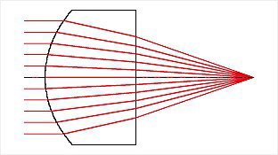
The axis of a linear polarizer determines the plane of polarization that the polarizer passes. There are two ways of finding the axis of a polarizer. A simple method is to start with a known polarizer with a marked axis. Place both the known and unknown polarizer together and transmit light through them. Rotate the unknown polarizer until no light passes through the pair of polarizers. In this orientation, the unknown polarizer's axis is 90° from the axis of the known polarizer.
If a known polarizer with a marked axis cannot be found, the axis can be found by taking advantage of the Brewster effect. When light reflects at glancing incidence off of a non-metallic surface, the S-polarization is reflected more than the P-polarization. A quick way to do this is to look at the glare off of a tiled floor or another non-metallic surface. Rotate the polarizer until the glare is minimized. In this position, the polarizer is oriented so that the axis is vertical. As an example, sunglasses use polarizers that have the polarization axis vertically oriented.
The value of transmission for a single polarizer refers to the percentage of the incident light that passes through one single polarizer. The value of transmission for parallel polarizers refers to the percentage of the incident light that passes through two polarizers, where the axis of polarization for each polarizer is aligned in the same direction. The value of transmission for crossed polarizers refers to the percentage of the incident light that passes through two polarizers, where the axis of polarization for each polarizer is separated by a 90 degree angle. The average value stated refers to the actual average of all transmission values from 400 to 700nm.
To create circularly polarized light, you require a circular polarizer. A linear polarizer by itself is not enough to create circularly polarized light. A circular polarizer is really just a linear polarizer followed by a quarter-wave plate (also known as a retarder) that is at 45° with respect to the axis of polarization.
In short, you can either use a circular polarizer, or combine a linear polarizer and retarder film to create circularly polarized light.
A single perfect polarizer will block 50% of incident light. Add in Fresnel reflections and you are at 42% transmission. For example, our TECHSPEC® Linear Polarizing Laminated Film transmits 38% for a single pass; so only about 4% is being lost to absorption. This is typical for linear polarizers because they are absorptive polarizers. Reflective, or refractive, polarizers like Glan-Thompson will have slightly better transmission, but these are typically not larger than 1” in size thereby limited the applications in which they can be employed.
In a birefringent material, such as a retarder, the fast axis is the axis through which the light travels faster. For a retarder, the fast axis is typically labeled and marks the axis on the retarder that is used as a reference for whichever desired effect is needed. For a ½ wave (½λ) retarder, the orientation of the fast axis is what determines the orientation of the linearly polarized light emitting from the retarder. For instance, if you rotate a ½ wave retarder 45° with respect to the linear polarized light entering the retarder, then the light emitted by the retarder will be rotated 90° from the incident polarized light. The slow axis in a retarder is the axis through which the light travels slower.
There is also a simple way to find the axes of a retardation plate. This requires two linear polarizers. Orient one linear polarizer so the axis is horizontal. Put the other linear polarizer in front of the first, oriented so that the axis is vertical. Place the retardation plate between the two crossed polarizers. Rotate only the retardation plate until maximum transmission is reached. The fast and slow axes will be at ±45° from horizontal.
To determine which axis is fast and which is slow, hold the retarder along one of the axes. For example, hold the plate by the left side and the right side. Rotate the retardation plate about this axis, so that the light is passing though a slightly thicker cross section of the retardation plate. Then repeat, using the other axis. If the color of the light changes from a bluish color to gray and then to black, then you are rotating about the fast axis. If the color changes from white to yellow and then to interference colors, then it is the slow axis.
To achieve the phase shift designated for any given retarder, the optical thickness of the material is selected to give the desired shift at a specific wavelength. Retarders are very wavelength dependent. Wavelengths close to the design or slight thickness differences will result in a slightly inaccurate phase shift of the transmitted beam. Since white light is composed of a range of wavelengths, no single material thickness can correspond to the proper shift across the entire region and, as a result the design must be generalized for the region of interest. The film material achieves the desired retardation for the visible due to its design at the center of the visible spectrum (560nm). Our quartz and film retarders are available in phase shifts of λ/2 and λ/4 in several wavelength options
When circularly polarized laser light passes through a Polarizing Cube Beamsplitter, P-polarized light is transmitted while S-polarized light reflected. On the other hand, when circularly polarized light passes through a Non-polarizing Cube Beamsplitter, the reflected and transmitted components contain the same polarization characteristics of the source beam. Namely, both the reflected and the transmitted components will be circularly polarized.
Multiple-order retarders (or waveplates) and zero-order retarders are interchangeable. Zero-order waveplates should be considered for more critical applications. The advantages of a zero-order waveplate include an increased bandwidth and a lower sensitivity to temperature changes. A ±2% change from the design wavelength will cause only a minor change in the retardation of a zero-order waveplate. With a multiple-order waveplate, a ±1% change from the designed wavelength will cause considerable problems with the retardation.
The polarization of light is changed when it is incident on a beamsplitter oriented at 45°. For randomly polarized input light, the S-polarization state is reflected more than the average amount of reflection and the P-polarization state is reflected less than the average. Plate beamsplitters are very sensitive to polarized light, the transmission of the S- and P-polarization states can each vary typically as much as 20% from the average at 550nm for a visible spectrum coating. Our dichroic cube beamsplitters are also extremely sensitive to polarization. The S- and P-polarization states can have a difference as large as 70%, while differing from the average transmission by approximately 20-30%. Beamsplitters should be selected carefully prior to integration into polarization sensitive applications. We do offer polarized cube beamsplitters that offer 92% reflection for S-polarization at 632.8nm.
Non-polarizing beamsplitters are primarily designed for polarization sensitive applications requiring 50% reflection and 50% transmission, when the polarizing effects need to be kept to an absolute minimum. They are typically optimized for a specific laser wavelength with the s- and p-polarization states of the transmitted beam differing by less than 5%. In essence, the coating does not change the polarization characteristics of the incident beam.
An easy way to determine if a retarder is a ¼λ of a ½λ is to use the set-up outlined below. First, transmit linearly polarized light through the retarder. This light can either come from a light source that is already linearly polarized or be randomly polarized light that is sent through a linear polarizer. After the light is passed through the retarder, it can have one of two characteristics: if the retarder is ¼λ, then the light is circularly polarized; if the retarder is ½λ, then the light is linearly polarized, but at a different angle than the incident light.
Finally, you can use a second linear polarizer (typically called an "analyzer") to determine which retarder you possess. Place the analyzer in the path of the light coming from the retarder and rotate it. If, at certain angles of rotation, the light being emitted from the analyzer gets more intense and then is completely blocked out, you have a ½λ retarder. If the light emitted is of similar intensity no matter how the analyzer is rotated, then you have a ¼ wave retarder. Please note that there are other types of retarders than ¼λ of a ½λ, and this test does not take that into consideration.
A retarder can be used at a different wavelength than the design wavelength and still maintain its phase, if it is tilted about its fast or slow axis. If tilted about the fast axis, the design wavelength can only be changed to a shorter wavelength. If tilted about the slow axis, the design wavelength can only be changed to a longer wavelength. To determine the amount of tilt required, use the following equation:
θ = sin-1 (λnew / λdesign) , where
θ = the angle on the output side of the retarder from the optical axis to the back surface of the retarder
Example: If a ¼λ retarder is tilted about the fast axis and it is designed at 1064nm, then it can still be used as a ¼λ retarder for a 670nm source if it is tilted by 39 degrees.
If on the other hand the retarder is not tilted and a wavelength other than the design wavelength is used, there will be a phase shift. A ¼λ retarder has a phase shift of 90°. A ½λ retarder has a phase shift of 180°. To determine the amount of the phase shift, use the following equation:
δ = 360° (Δ n τ / λ ) , where
δ = the retardation angle
Δ n = the birefringence factor
τ = the thickness of the sheet
λ = the wavelength of light
Example: For a ¼λ retarder, since the phase shift (δ ) is 90°, Δ nτ = ¼ = 140nm (for λ =560nm). So if a source at 850nm is used for a ¼λ retarder with a design wavelength of 560nm, then δ = 360° multiplied by (140nm/850nm)= 59.29°. Solving now for Δ nt is (δ λ / 360°)= λ (59.29° / 360°) = 0.165λ » λ /6, the phase shift.
Traditionally, the birefringent materials of choice for retarders have been naturally-occurring crystalline materials such as calcite, mica and quartz. Some applications now require performance versatility beyond what these crystals can offer. Using birefringent polymers for polarization control offers a unique combination of high performance and cost-effectiveness.
Precision polymer retarders feature carefully aligned birefringent polymer sheets laminated between two precision BK7 windows. Polymer materials offer a lower birefringence than quartz and can therefore be made into true zero-order retarders of reasonable thickness. They also offer excellent angular field-of-view since they are true zero-order retarders.
Polymer retarders are much less sensitive to incidence angle than quartz retarders. The curve below compares the change in retardance as a function of incidence angle for polymer and quartz retarders. A polymer retarder changes by less than 1% over a ±10° incidence angle.
The temperature sensitivity of laminated polymer retarders is about 0.04% per °C, allowing operation over moderate temperature ranges without significantly degrading retardance accuracy.
Optical Prisms
Edmund Optics® offers the following types of prisms: right angle, penta, amici roof, Schmidt, dove, littrow, equilateral, trihedral (retroreflection), rhomboid, anamorphic, wedge, light pipe homogenizing rods and compound parabolic concentrators.
Right angle prisms deviate line of sight by 90°.
Penta prisms, half penta prisms, and amici prisms deviate line of sight by 90° without inverting or reverting images; their geometric shapes lend each to different applications.
Schmidt prisms deviate line of sight by 45° while inverting and reverting images.
Dove prisms rotate images by twice the prism rotation angle.
Littrow prisms can be used in two ways: uncoated littrow prisms disperse white light into its component colors and coated littrow prisms deviate line of sight by 60°.
Equilateral prisms disperse white light into its component colors.
Trihedral prisms, or retroreflection prisms, produce 180° beam reflection.
Rhomboid prisms displace the optical axis without inverting images.
Anamorphic prisms expand the incident beam diameter in one direction.
Wedge prisms can be used individually or in pairs: individually, it is used to deviate a laser beam by a set angle, or in pairs, they create an anamorphic prism pair.
Light pipe homogenizing rods homogenize non-uniform light sources. Tapered light pipes also reduce output NA.
Compound parabolic concentrators work similarly to light pipe homogenizing rods; they collect and homogenize light from divergent sources.
The distance through glass, such as that used to manufacture our Right Angle Prisms, relate to an equivalent distance through air via a simple equation. Take the distance traveled through glass (d) and multiple it be the refractive index of the glass (nd) to get the equivalent distance through air, or Optical Path Length (OPL):
d x nd = OPL
Yes, a pair of wedge prisms can steer a beam anywhere within a circle described by the full angle 4θ, where θ is the deviation from a single prism. This beam steering is accomplished by rotating the two wedge prisms independently of each other, and is typically used to scan a beam to different locations in imaging applications. Two wedge prisms can be used as an anamorphic pair for beam shaping (to correct the elliptical shape of diode outputs).

Yes, we do have a stock lens solution for this. Cylinder Lenses placed one in front of the other, at the right distances, will invert the vertical dimension while maintaining the orientation of the horizontal. By taking two positive cylinder lenses and separating them by the sum of their focal distances, you will achieve a system that inverts the image without reversing it. The downside is that the resultant image isn’t very sharp which is what one would expect from what is basically a really inexpensive, one-dimensional Keplerian telescope.
Another, much simpler option is to use a Dove Prism. Dove prisms are used in binocular and telescopic systems to invert images in exactly the way mentioned. It's a simple, one-piece solution to your problem. It requires no focusing and is not as expensive as two cylinder lenses; but it is much bulkier than two cylinder lenses and would have to be placed very close one’s eye in order to work.
Beamsplitters
To use our #58-877 25mm Cube Beamsplitter Adapter, it is necessary to use the #58-854 TECHSPEC® 1” Diameter Kinematic Mount; the #58-872 TECHSPEC® C-Mount Kinematic Mount, or any other Kinematic mount will not work. This is because the 25mm Beamsplitter Adapter is specifically designed to fit into the 1” Diameter Circular Kinematic Mount where the Nylon-tipped locking screw will secure it into place.
Our line of C-Mount Kinematic Mounts can be integrated with any C-Mount Component; correspondingly, the same applies to our line of T-Mount Kinematic Mounts with any T-Mount Component.
A beamsplitter is an optical component that divides light (i.e., a beam) into two separate portions (beams). When the component is inserted into an optical path at a specific angle (typically 45°), a portion of the beam will be diverted (reflected) in a different direction (typically 90° from the input beam). A beamsplitter will reflect a portion of the incident energy, absorb a relatively small portion, and transmit the remaining energy. It is essentially an optical window (clear glass or film) that has a metallic or dielectric coating on one side with specific reflecting and transmitting characteristics. A plate beamsplitter is the most common type and has a thin glass substrate. They are also known as "mirror-type" beamsplitters due to the reflective nature of the coatings used. We offer plate beamsplitters with the most common reflection percentages (30%, 50%, and 70%), as well as a variety of others. The reflective coating is optimized at 45°. An anti-reflection coating is available on the back surface of many of the beamsplitters and it is also optimized at 45°. The spectral curves shown with the product are for the average of the S- and P-states of polarization. It should be noted that these types of beamsplitters are very sensitive to polarized light.
A pellicle is a very thin optical-grade nitrocellulose membrane (or film) stretched over an aluminum ring and bonded in place. In function, a pellicle beamsplitter serves the same purpose as a common plate beamsplitter. Upon close inspection, a plate (or "mirror-type") beamsplitter produces two reflected beams for a single input beam. One is a reflection off the first (or front) surface and the second is off the second (or back) surface. The result is what is called a "ghost image" or secondary reflection. In addition, plate beamsplitters slightly displace the transmitted beam laterally from the input beam due to the thickness of the glass substrate (1-3mm depending on size). For these reasons, plate beamsplitters minimize these effects and offer the best performance when the glass thickness is minimal, the coated surface is oriented toward the source, it is inserted in a collimated beam, and the back surface is AR (anti-reflection) coated. Pellicles on the other hand eliminate ghost images because of the thinness of the membrane (2 microns), since the first and second surface reflections are superimposed. In addition, absorption is imperceptible. Pellicles can be used uncoated as well as coated for several different reflection percentages. Also because of their lightweight, pellicles can be used when weight issues prevent the use of heavier plate or cube beamsplitters. However, since pellicles are extremely delicate, they have several drawbacks. The membrane can be easily broken (and cannot be repaired), thus they require caution in handling and mounting. Pellicles are also very sensitive to mounting stresses and atmospheric vibrations (including acoustic noise and compressed air), both can cause the film to warp or vibrate and therefore result in reflection and transmission distortions. Pellicles are highly desirable for interferometric applications since there are no ghost images, no change in the optical path length, and no chromatic aberrations with converging beams. However due to their cost and delicate nature, they are often not selected for the majority of applications requiring a beamsplitter.
A cube beamsplitter is essentially two identical right angle prisms where the hypotenuse of one of the prisms is coated with a semi-reflective coating before the two prisms are cemented together to form a cube. Cube beamsplitters offer several advantages over plate beamsplitters. They are easier to mount, since the 45 degree reflecting surface is within the cube and it can be mounted flush. Since a plate beamsplitter is mounted from the edges of a thin glass, it cannot handle as much deformation from mounting stresses without affecting the performance. The reflective coating is within the cube, so it is naturally more durable and has a longer lifetime than for a plate beamsplitter. Also there are no ghost images, since most of the reflections within a cube are reflected back in the direction they came and thus do not effect the output beams/images. However because converging and diverging beams add considerable image quality errors, cube beamsplitters should only be used in collimated beams. Additionally, since cube beamsplitters are heavier, they should be considered carefully for weight sensitive applications. Just like all beamsplitters, (the prism with) the reflective coated surface should face the input beam or source. Our cube beamsplitters are available with dielectric coatings as dichroic cubes for 50% reflection at 550nm or as polarizing cubes with 92% reflection for S-polarization at 632.8nm. All other polished outside surfaces are anti-reflection coated to minimize ghost images.
Unfortunately, no. All coatings used are optimized for certain portions of the spectrum. Our beamsplitters use partially reflecting coatings designed for broadband applications in the visible spectrum and are optimized for a 45° angle of incidence. The visible spectrum in reference to coating performance typically covers the range of 450nm to 650nm, while our spectral curves typically give extended values from 400nm to 700 or 800nm. Percentage values stated are typically held within ±10% over the visible spectrum, while within ±5% at the optimized wavelength, typically 550 or 632.8nm. To determine the performance of a particular beamsplitter for an application, the reflection and transmission values should be closely inspected for the particular wavelength(s) of interest. For example, a plate beamsplitter with a 50/50 ratio will actually have a value of 35% average reflection at 800nm. Our dichroic cube beamsplitters have almost equal average amounts of reflection and transmission over the visible range. Variations in reflection or transmission values over the spectrum are typically due to the inherent characteristics of the type of coating used: metallic, dielectric, or hybrid.
Yes. A variable density beamsplitter has linearly varying reflection and transmission percentages across its length. Actually any neutral density filter with a metallic coating (typically inconel) can be used as a beamsplitter. Catalog values state optical densities at a 0° (or normal) angle of incidence, which can be quickly converted to transmission values (see Frequently Asked Questions on filters). The coating is designed to transmit a specific amount of energy, but as a result of the metallic coating a certain amount will be reflected. When using a filter of this nature as a beamsplitter, please note that absorption characteristics and changes of angle (0° to 45°) will dramatically affect the actual reflection/transmission energy split. Edmund Optics offers a linear Variable Density Beamsplitter that is primarily used as a variable neutral density filter.
Edmund Optics® offers three main types of cube beamsplitters: polarizing, non-polarizing, and lateral displacement. Polarizing cube beamsplitters divide unpolarized light into two orthogonally polarized beams. They are typically used in laser beam separation/combination applications, laser mirrors for beam steering, and semiconductor and photonics instrumentation. Non-polarizing cube beamsplitters divide light evenly, regardless of polarization. They are used in laser mirrors for beam steering, optical interferometry, and biomedical instrumentation. Lateral displacement beamsplitters split incident light beams into two displaced, parallel beams; they can be thought of as a sub-type of polarizing cube beamsplitters since the displaced beam is S-polarized while the other is P-polarized.
Polarizing | Non-Polarizing | Lateral Displacement |
---|---|---|
![]() |
![]() |
![]() |
A plate beamsplitter is the most common type of beamsplitter. It features a thin glass substrate. The reflective coating is typically optimized at 45°, and an anti-reflection coating is commonly applied to the rear surface. Similar to cube beamsplitters, plate beamplitters also come in polarizing and non-polarizing types. Polarizing plate beamplitters split the input beam into two orthogonal components; P-polarized light is transmitted while S-polarized light is reflected 90° to it. Non-polarizing plate beamsplitters split the input beam into two orthogonal components; average, P-polarized and S-polarized states are transmitted and reflected equally. Dichroic plate beamsplitters reflect one portion of the spectrum while transmitting the other. They are ideal for splitting or combining specific wavelengths of light, depending upon the application setup. Polka-dot plate beamsplitters offer specific reflection/ transmission ratios. They have a constant reflection-to-transmission ratio over a large spectral range, making them ideal for use from UV to mid-IR. They are also not angle sensitive so they are great for splitting energy from a radiant light source. Pellicle beamsplitters offer specific reflection/ transmission ratios as well. Due to their ultra-thin nitrocellulose membrane construction, there are no ghost images from second surface reflections, no chromatic aberration with converging beams, and no change in optical path length. Elliptical plate beamsplitters maximize beamsplitter efficiency while maintaining required mounting space. When oriented at 45° they create a circular aperture equal to the diameter of the minor axis.
Polarizing | Non-Polarizing | Lateral Displacement |
---|---|---|
![]() |
![]() |
![]() |
Usually, reflection/transmission curves shift and broaden asymmetrically when the Angle of Incidence (AOI) is changed. Beyond the stated specifications, R/T ratios decrease as AOI is decreased.
When circularly polarized laser light passes through a Polarizing Cube Beamsplitter, P-polarized light is transmitted while S-polarized light reflected. On the other hand, when circularly polarized light passes through a Non-polarizing Cube Beamsplitter, the reflected and transmitted components contain the same polarization characteristics of the source beam. Namely, both the reflected and the transmitted components will be circularly polarized.
The polarization of light is changed when it is incident on a beamsplitter oriented at 45°. For randomly polarized input light, the S-polarization state is reflected more than the average amount of reflection and the P-polarization state is reflected less than the average. Plate beamsplitters are very sensitive to polarized light, the transmission of the S- and P-polarization states can each vary typically as much as 20% from the average at 550nm for a visible spectrum coating. Our dichroic cube beamsplitters are also extremely sensitive to polarization. The S- and P-polarization states can have a difference as large as 70%, while differing from the average transmission by approximately 20-30%. Beamsplitters should be selected carefully prior to integration into polarization sensitive applications. We do offer polarized cube beamsplitters that offer 92% reflection for S-polarization at 632.8nm.
Non-polarizing beamsplitters are primarily designed for polarization sensitive applications requiring 50% reflection and 50% transmission, when the polarizing effects need to be kept to an absolute minimum. They are typically optimized for a specific laser wavelength with the s- and p-polarization states of the transmitted beam differing by less than 5%. In essence, the coating does not change the polarization characteristics of the incident beam.
Diffraction Gratings
Concave grating mounts can be monochromatic or spectrographs (polychromatic). Two common concave grating mount configurations are Rowland circle spectrographs and polychromator mounts (also known as flat-field spectrographs). Edmund Optics® offers Zeiss Concave Diffraction Gratings in both configurations.
In a spectrometer using a Rowland circle mount, the entrance slit, illumination source, and the center of the concave grating all lie on the Rowland circle, which has a diameter equal to the tangential radius of the grating curvature. This mount was designed in 1883 by Henry A. Rowland, who was also the first to rule concave gratings of spectroscopy grade quality. Spectra recorded using this mounting configuration are generally free from defocus and primary coma across the wavelength range and spherical aberration is negligible. However, astigmatism can cause issues with the efficiency of the instrument, as a significant fraction of the diffracted light is lost. Therefore, Rowland circle configurations are best suited when a light source with high intensity is used.
Spectrometers with polychromator mounts (flat-field spectrographs) use a fixed arrangement of the entrance slit, concave grating, and flat image plane, which is a linear detector array covering wavelengths of interest. The flat image plane is made possible by changing the groove pattern of the holographic grating by varied line-spacing (VLS) or interferometric methods, which change the focus plane of the grating from a curved shape to a flat surface. This maintains resolution while reducing aberrations such as astigmatism. Instruments with polychromator mounts have a higher light collection efficiency and offer high resolution on flat imaging sensors.
One of the main advantages of using a concave grating in both Rowland circle and polychromator configurations is that, unlike instruments that use plane gratings, no additional focusing optics, such as spherical concave mirrors, are required.
There are two types of curves that can be used to predict diffraction efficiency: an absolute efficiency curve and a relative efficiency curve. Absolute efficiency curves plot the amount of light that will be diffracted into a specified order (as a percentage of the incident monochromatic radiation on the grating) for any given wavelength. All curves in our catalog are for absolute efficiency in the first order using aluminum coated gratings. The curves also represent an average of the S and P-states of polarization. For gratings coated in gold, a 15-20% increase in absolute efficiency can be expected from 700nm to 1100nm.
The ratio between the absolute efficiency and the amount of light reflected by a plane mirror with the same coating as the grating is the relative efficiency. Thus relative efficiency curves consider the performance of the coating used on the grating. Relative efficiency does not account for the strengths and weaknesses of specific coating types.
A diffraction grating is an optical component that in normal use separates (diffracts) polychromatic (white) light into its component wavelengths. Each grating is fabricated from a highly accurate master grating that is copied many times. Since this same replication process makes all of our gratings, they are known as replicas. Ruled and holographic gratings are different, not only in the way their master gratings are manufactured but also most noticeably in the profile of each surface. Both types have a series of closely spaced, straight parallel grooves in a mirror coating with a flat glass substrate. Ruled gratings have a sawtooth-shaped groove profile tilted at a specific angle (the blaze angle) that is designed to have maximum efficiency at a specific (blaze) wavelength. Holographic gratings however have a sinusoidal cross-section. Because of this sinusoidal pattern, they cannot be blazed easily and their efficiency is usually less than a comparable ruled grating. However, when the groove spacing to wavelength ratio is nearly one, holographic gratings have virtually the same efficiency ruled gratings. Due to an optical manufacturing technique, master holographic gratings also produce less stray light than mechanically fabricated master ruled gratings, since they are free from spacing errors that cause ghost reflections in ruled gratings.
The grating equation is an expression that can be used to calculate the diffraction angle from light incident to the grating's grooved surface for a particular order, given the wavelength and angle of incidence for that light. By knowing where the light will be diffracted, the grating can be rotated to redirect the light to a desired location. The grating equation and accompanying illustration is shown below:
A grating separates polychromatic (or multiple wavelength) light into its component wavelengths by diffraction. Diffraction is a process in which light incident to a surface with dimensions similar in size to its wavelength is dispersed at certain angles. This diffraction angle is dependent upon the wavelength of light (see the grating equation above). Thus, polychromatic light will have a separate diffraction angle for each individual wavelength. This difference in diffraction angle is what separates light into its component wavelengths. In a transmission grating the diffracted light is passed through at an angle equal to the diffraction angle. For reflective gratings, the light is first diffracted by the grating and then reflected by the coating at an angle equal to the diffraction angle. Both reflective and transmission gratings follow the diffraction grating equation.
The sawtooth shaped groove profile of a ruled grating (the longer face) forms a specific angle relative to the surface of the flat substrate. This angle is known as the blaze angle. The wavelength of light that yields the greatest absolute efficiency of the ruled diffraction grating is called the blaze wavelength. Light equal to the blaze wavelength will have a diffraction angle equal to the blaze angle when the incident angle of the light is also equal to the blaze angle.
Imperfections in the surface of a diffraction grating can cause light to be scattered at an angle different from the diffraction angle. This is typically known as stray light. Stray light (also called ghosts or scattered light) is primarily due to errors in the groove spacing. Since master ruled gratings are fabricated mechanically, they generate more stray light than optically manufactured master holographic gratings. Stray light will interfere with the rest of the light being diffracted correctly off the grating.
Special care must be taken when handling and cleaning gratings. Handle only by the edges. Because the grooves are very tiny and delicate, the "drag method" for cleaning should not be used. Gratings have relatively soft coatings and are especially vulnerable to fingerprints and numerous aerosols, which can cause permanent damage.
Unfortunately, the grating itself will not be able to resolve any more. The number of groves is divided by the size of the spot to determine the resolving power. You could use a higher groove/mm grating, or a larger spot size to increase the resolving power.
Optics Assemblies
The information required to design with our lenses is provided with each lens listing in both our printed and online catalog. A detailed downloadable file of the prescription data for all the TECHSPEC® lenses that are available in our catalog, can be found on our Prescription Data page. If you have any questions regarding this information, you can always speak to one of our engineers.
We have an Achromat Prototyping Assembly that can be used to create your own imaging system with any of our 12.5mm diameter achromatic lenses. A variety of f/#s are possible with the use of different selectable apertures. The lens cell accepts two achromats and threads directly into our Helicoid Barrel while retainers are used to fix the relative position of the cell. Coupled with our other C-Mount components, many variations can be created to fit your application needs.
Fiber Optics
To couple light from a source into a fiber, a Ball Lens or lens with a positive focal length can be used. If the light is collimated, the lens must have a f/# greater than or equal to 0.5/NA, where NA is the numerical aperture of the fiber. The f/# of the lens is equal to f/D where f is the lens focal length and D is the beam diameter, not the diameter of the lens. This insures that the cone of light entering the fiber is within the fiber's acceptance angle. It should be placed away from the fiber at a distance equal to the lens focal length. A ball lens placed in contact with the fiber can also help couple light into the light guide. Its NA must be less than or equal to the NA of the fiber. This insures that the light is effectively coupled into the light guide. If the source is not collimated, i.e. light emitting from another fiber with a similar numerical aperture, one ball lens can be used to first produce a more collimated output beam and then another identical ball lens can be used to couple that light into the other fiber. The ball lenses should be placed in near contact to maximize efficiency.
Optical fibers do not produce beam-like outputs, but rather quickly diverging cones of illumination. They are very good for transmitting light because the fiber core is of a higher index of refraction than the cladding. This index difference not only keeps light in the fiber, but also defines the largest angle of light that the fiber can accept. Due to symmetry principles in fiber optics, the output angle of a fiber is approximately the same as the input angle. The full acceptance angle is defined as the maximum allowable input/output angle for each optical fiber and is directly related to the numerical aperture specification (NA). Our typical acrylic fibers will accept a cone of light approximately 61°, 56° or 35°, which correspond to 0.51, 0.47 and 0.3 NA values respectively. If the input angle, say 30°, is smaller than the acceptance angle, say 61°, then the output angle will still be 30°, not the 61° that one might think. If a fiber is overfilled, the output angle will be slightly less than the acceptance angle due to losses.
A lens with a positive focal length can help reduce the divergence angle of an output beam from an optical fiber. The lens must have a f/# less than or equal to 0.5/NA, where NA is the numerical aperture of the fiber. The f/# of the lens is equal to f/D where f and D are the lens' respective focal length and diameter. This insures that the lens will capture the cone of light exiting the fiber. It should be placed away from the fiber at a distance equal to the lens' focal length. A Ball Lens placed in contact with the fiber can also reduce the divergence angle of the output beam.
The numerical aperture (NA) of a fiber is a number that defines its light gathering capability. A larger NA corresponds to a larger acceptance angle, which results in the ability to collect more light. The NA can be calculated from the index of refraction values for the fibers core (ncore) and cladding (nclad).
NA = v (ncore2 - nclad2)
Optical fibers have several characteristics that contribute to loss in transmission. The most common are cladding loss between the core and cladding diameters, packing fraction loss due to gaps between individual fibers in light guides and fresnel losses due to reflections off the end faces. Additional factors include extreme bends over long durations, fracture cracks due to bending, and cross-talk between individual fibers.
Attenuation is a decrease of light intensity within a fiber, usually due to absorption and scattering losses. This loss of power is measured in decibels (dB) where
dB = 10*log (Pin/Pout)
where:
Pin, Pout are the input and output powers.
The affects of these losses increase with fiber length. The value dB/m measures power lost in dB for every meter of fiber. Edmund Optics' attenuation curves measure the power loss in dB/m for our Communications Grade Optical Fibers and dB/km for our Optical Grade Fibers across the visible spectrum. For example, our 1000 micron diameter Communications Grade Optical Fiber has an attenuation of approximately 0.1dB/m at 600nm. If you were to use a 2-meter fiber, then the total loss would be 0.2 decibels. If we had an input power of 100mW, the output power would then be 95.5mW, resulting in a 5.5% loss. Resultant output power of a fiber, given its attenuation, can be calculated using the equation below:
Pout = Pin * 10-dB/10
The major difference between jacketed and unjacketed optical fibers is durability. Because transmission through an optical fiber is dependent upon the reflection of light off the cladding, any nicks or scratches in the cladding could cause back-reflections and light loss. Jacketed fibers help prevent any damage to the cladding. Jacketed fibers are recommended in applications where there is a possibility of even minor damage to the fiber. Unjacketed fibers are recommended for applications where a jacketed fiber's larger diameter or heavier weight are not practical. Unjacketed fibers are also known as fiber strands, whereas jacketed fibers are also known as light guides. Jacketed fibers can consist of one or more fiber strand and the jacket coating is typically a black polyethylene material.
There are a specific number of ray paths that can efficiently propagate through a fiber. These ray paths are called modes. The amount of modes a fiber can support is a function of the core size, in addition to other factors. The core diameters of single-mode fibers are smaller than multimode fibers. A multimode fiber can support many modes a single-mode fiber only allows one mode to be transmitted over large distances without great loss, because this mode travels without any reflections from the core-cladding interface. Edmund Optics' Optical Grade and Communications Grade fibers are all multimode.
"Cross-talk" is when light is scattered from one fiber optic strand to another within a jacketed fiber bundle (or light guide) consisting of several fiber optic strands. It is strongly associated with packing fraction losses. This occurs in both coherent and incoherent fiber bundles. It is typical eliminated by using an absorbing material between the fiber strands or special coating the fiber strands. This is particular noticeable in coherent fibers, where the end faces look almost like a "honeycomb" or grid pattern, because a black absorbing fiber (known as Mural Absorption Fibers, or EMA) is used between the imaging fibers.
"Cross-talk" can also occur when unwanted light from one unjacketed fiber optic strand scatters to another, when they are aligned side-by-side. This is common in communication applications when two fibers transmitting separate signals are in close proximity. Increasing the lateral distance between fiber optic strands and/or using jacketed fibers can eliminate this affect. Our jacketed Fibers Optics do not suffer from cross talk.
Using an optical fiber cutting block or optical fiber hot knife, one can cut plastic jacketed and unjacketed fibers. A cutting block insures that the plastic fibers are cut perpendicularly, which minimizes loss due to scattering. A hot knife is simply a heated blade that yields clean terminations. It also polishes plastic fibers as it cuts them by using the heat to fuse the glass. Pressing the ends of plastic fibers perpendicularly against a hot plate can also provide effective polishing. Edmund Optics offers both an Optical Fiber Cutting Block and an Optical Fiber Hot Knife.
Grinding glass fiber ends with an abrasive material, such as sandpaper, can produce an effect polish for glass fibers. Best results can be achieved by taking a very fine grit sandpaper, wetting the sandpaper slightly, and, while holding the optical fiber perpendicular to the sandpaper, polish the fiber in a "figure-8" motion. The figure-8 motion allows the fiber to be polished evenly on all edges and the moisture prevents the fiber from being nicked by large grit on the sandpaper.
Optical fibers are specifically designed not to allow light to escape from the sides; this is why they may be used for communications purposes. Bending a fiber into a tight radius, however, increases the angle in which the light strikes the inside of the cladding, allowing some light to exit out of the fiber. Removing part of the cladding layer around the core by abrasion may also produce the desired effect, but starts to change the component from a fiber optic plastic strand to just a plastic strand.
In a bundle of fibers, if the relative position of each individual fiber at one end of the bundle is exactly the same as those at the other end, then the fibers are said to be coherent. Coherent fiber bundles such as those in our Fiber Optic Tapers are used to relay an image from one end of the fiber to the other, whereas incoherent fiber bundles cannot. Incoherent fibers are primarily used to transmit light or signals rather than images.
The radius a fiber optic strand or light guide can be bent without risking breakage or increased attenuation is called the bend radius. Edmund Optics® lists the bend radius for all its optical fibers and light guides.
There are 3 possible solutions to maximize the amount of light when coupling light from a LED to a fiber. First, using Infinity Corrected Microscope Objectives in retro position; this works well but is by far the most expensive solution. Second, we offer Fiber Optic Collimator/ Focuser Assemblies, available with an SMA or FC connector for VIS, VIS-NIR and IR wavelengths. You can achieve spot sizes of a few microns. This product offers the best value for its price. Last, but not least, are Ball Lenses; these are the least expensive solution. When coupling light from a LED into a fiber, the choice of ball lens is dependent on the Numerical Aperture (NA) of the fiber and the LED’s spot diameter. The LED’s spot diameter is used to determine the NA of the ball lens. The NA of the ball lens must be less than or equal to the NA of the fiber in order to couple all light into the fiber. The tricky thing with ball lenses is alignment. View Understanding Ball Lenses for additional information and useful equations.
The output beam would be scattered according to the numerical aperture (NA). This in terms of angle of the fiber is equal to sin-1(NA) = θ. For example, if your numerical aperture is 0.22 then the angle at which the beam will exit the fiber is 12.7°. The only time this would not occur would be if macro-bending was not present and the fiber was perfectly straight. In this perfect, theoretical case, the beam will emerge collimated. However, in most cases, if there is even any movement off a straight axis, the output of the fiber will exit at a cone angle comparable to the NA.
If you introduce linearly polarized light into a multimode fiber it will become randomly polarized at the exit face because of the many internal reflections it undergoes within the fiber; the same is also true for singlemode fibers. Adding a polarizer to the fiber’s output end will turn the randomly polarized light into the linear that you desire. Polarization maintaining fibers exist as well, though Edmund Optics® does not offer any.
There are multiple ways to achieve the effect you require; however, the most straightforward is utilizing Darkfield Illumination. Darkfield Illumination is ideal for imaging transparent or translucent objects. Light from the Darkfield illuminator, usually a special type of ring light guide, enters the object through the edge, rather than from above, enabling one to see the object’s profile. View Choosing the Correct Illumination for additional information on pros and cons of various illumination setups.
The Optical Fibers that we sell curl back upon themselves because they are stored, typically for long periods of time, in spools which force the fibers to retain a curved shape. The best way to “uncurl” these fibers is to lay them out straight and use a heat gun to heat up the fibers, and then let them cool in a straight shape. Most fibers, such as the ones that we carry, will retain their straight shape for quite some time afterward.
Infrared Optics
Edmund Optics® offers a variety of substrates for UV and IR applications, including BK7, fused silica, sapphire, calcium fluoride, zinc selenide, silicon, germanium and magnesium fluoride. These substrates are available on many of our stock lenses, windows and a host of other optics.
BK7 is a low cost substrate for visible and NIR applications. It is generally not favored for UV, though it offers good transmission down to 350nm. It is great for machine vision, microscopy, and industrial applications.
Fused silica has a low coefficient of thermal expansion and excellent transmission from UV to IR. It is great for interferometry, laser instrumentation, spectroscopy, and industrial applications.
Sapphire is extremely hard and durable with good transmission from UV to IR. It is great for IR laser systems, spectroscopy and rugged environmental equipment.
Calcium fluoride has low absorption and high damage threshold from 0.2 – 7μm. It is great for spectroscopy, semiconductor processing, and cryogenically cooled thermal imaging.
Zinc selenide has a low absorption coefficient and high resistance to thermal shock. It is great for CO2 laser systems and thermal imaging.
Silicon is a low cost and low density substrate for weight sensitive IR applications. It is great for spectroscopy, mid-IR laser systems, and THz imaging.
Germanium has a high index of refraction and knoop hardness with transmission in the mid and far-IR regions. It is great for thermal imaging, FLIR, and rugged IR applications.
Magnesium Fluoride is extremely rugged and durable with excellent broadband transmission from the DUV to mid-IR regions. It is great for UV and IR laser systems, rugged environmental equipment, and high vibration environments.
Substrate Comparison Chart

Germanium is fairly non-reactive except with strong oxidizing agents. Both high temperatures and high vacuums can cause germanium to react with ethanol, but under normal conditions, ethanol and acetone are both safe to use on our germanium, including any of the lenses and windows that Edmund Optics® provides.
Ultraviolet Optics
Many overlook BK7 as a viable material for near-UV applications even though it can transmit down to about 300nm. Nonetheless, BK7’s transmission begins to dip around 340nm. There are some variables when it comes to the source of BK7, though it can be recommended for use above 350nm. When in doubt, sapphire and UV fused silica are the best options, they offer high transmission from UV to visible to NIR wavelengths.
Edmund Optics® offers a variety of substrates for UV and IR applications, including BK7, fused silica, sapphire, calcium fluoride, zinc selenide, silicon, germanium and magnesium fluoride. These substrates are available on many of our stock lenses, windows and a host of other optics.
BK7 is a low cost substrate for visible and NIR applications. It is generally not favored for UV, though it offers good transmission down to 350nm. It is great for machine vision, microscopy, and industrial applications.
Fused silica has a low coefficient of thermal expansion and excellent transmission from UV to IR. It is great for interferometry, laser instrumentation, spectroscopy, and industrial applications.
Sapphire is extremely hard and durable with good transmission from UV to IR. It is great for IR laser systems, spectroscopy and rugged environmental equipment.
Calcium fluoride has low absorption and high damage threshold from 0.2 – 7μm. It is great for spectroscopy, semiconductor processing, and cryogenically cooled thermal imaging.
Zinc selenide has a low absorption coefficient and high resistance to thermal shock. It is great for CO2 laser systems and thermal imaging.
Silicon is a low cost and low density substrate for weight sensitive IR applications. It is great for spectroscopy, mid-IR laser systems, and THz imaging.
Germanium has a high index of refraction and knoop hardness with transmission in the mid and far-IR regions. It is great for thermal imaging, FLIR, and rugged IR applications.
Magnesium Fluoride is extremely rugged and durable with excellent broadband transmission from the DUV to mid-IR regions. It is great for UV and IR laser systems, rugged environmental equipment, and high vibration environments.
Substrate Comparison Chart

Laser Optics
Laser optics are a group of optics that have been designed and manufactured for use in laser applications. Optical components used for more general purposes may be manufactured from more common glass types and may have broadband coatings or be uncoated to be compatible with many different wavelengths. Conversely, because lasers typically have very narrow wavelength ranges or wavebands (ignoring harmonics), laser optics materials and coatings usually contain more exotic materials which are used to optimize the component for the specific design wavelengths of the application. Moreover, there are a number of highly specialized applications which involve high-power or ultrafast lasers. These applications require laser optics components with extremely low tolerances for characteristics including absorption, dispersion, thermal conductivity, laser-induced damage thresholds (LIDT), surface quality, coating properties, and much more.
Increasing the diameter of optical components reduces power or energy density in a system, reducing the likelihood of laser-induced damage in high-power systems. Learn more in our Large Aspheres: Enabling High-Power Optical Systems application note.
Polarization refers to the direction with which the electric field of light waves oscillate, which is perpendicular to the direction of propagation. Light waves can be linearly, circularly, elliptically, or randomly polarized. For more information about polarization read Introduction to Polarization.
Laser sources may be polarized due to anisotropy (a material property that is different in different directions) in the laser gain material, directionally dependent polarization losses in the laser resonator, or the use of birefringent optical materials. Some laser sources are unpolarized (e.g. fiber lasers). The polarization state of a laser can also be used to reduce unwanted and potentially dangerous reflection from high-power sources as some materials reflect or absorb light in certain polarizations states over others.
Many laser applications including some interferometry, optical amplification and modulation, nonlinear frequency conversion, and incoherent and coherent polarization beam combining (polarization coupling), depend on the state of polarization in order to function.
A laser beam expander is designed to provide larger collimated beams in order to decrease spot sizes at large distances. Not only will the beam size be increased by a certain factor, but the beam divergence will also be decreased by the same factor. The result is a smaller spot size at long distances when compared to what the laser could produce by itself. For a more detailed explanation of the advantages of laser beam expanders, view Beam Expanders.
A refractive line generator uses a cylinder or rod lens to focus a laser in only one axis only (drop-moved placement) in order to create a line of light. A diffractive line generator uses a flat optic with an etched microstructure that breaks apart a laser beam and forms an interference pattern in the shape of a laser line. Refractive optics do not correct for the inherent Gaussian profile of a laser beam and form a line with a "hot spot" in the center and fading edges. Diffractive optics will create a line that is uniform in thickness over its length, but is segmented. Diffractive line generators also cause a small portion of the light to be redirected into different diffractive orders, which causes additional faint lines to appear. Some laser line generators use a unique patented Powell glass lens design in order to achieve a continuous (not segmented) line with an even distribution along the length of the line.
Though we don’t have a complete package to automatically modulate beam waist, we do offer laser beam expander systems that allow one to focus down the spot size of a laser source. You could attach, for example, one of our laser beam expanders to a motor for them to automatically adjust the spot size of a laser.
Reflective laser beam expanders are achromatic by design. This enables them to easily be used for broadband applications including those using multiple laser wavelengths or for tunable lasers. This achromatic nature makes them ideally suited for ultrafast applications or for wavelengths that are difficult to find transmissive designs for, such as certain QCL wavelengths.
Reflective laser beam expanders are suited for most types of lasers. TECHSPEC Monolithic Reflective Beam Expanders (Mark I) are not designed for use with high power lasers, but are suitable for any laser with a beam size smaller than the aperture, including Nd:YAG lasers, Quantum cascade lasers, Ti:Sapphire ultrafast lasers, and fiber lasers at various wavelengths into the IR. For more information, please contact our technical support.
Laser Diode Modules are the simplest commercial packaging for laser diodes. They consist of the actual diode, a photodiode for monitoring output, and the can that holds them. Unfortunately, there is no single “best” lens to focus or collimate their output. Lasers diodes pose special challenges because their outputs are irregularly shaped (elliptical rather than circular) and vary widely amongst the on the market. It is difficult to compensate for these factors with a single lens and therefore the best lens will depend on the specifications of one’s laser diode (e.g. the beam divergence in each axis) as well as the desired beam characteristics (e.g. desired spot size and distance). In many cases, the desired results can only be obtained with multiple elements. Luckily, if the main concern is beam quality without the need for a custom multiple-element solution, Edmund Optics® offers many Laser Diode Modules and other packaged diode lasers that come with the diode and integrated optics to maximize the quality of the beam.
These laser beam expanders offer two different mounting options. There are ¼-20 through holes, which can hold the laser beam expander on its side so the optical axis of the part is parallel to your table. Additionally, there are 6-32 threaded holes on the bottom of the laser beam expander that can also be used.
Ideally, they would be mounted to a goniometer to reach the optimal alignment with respect to your input beam in order to reach the specified wavefront performance. However, in cases where a user is looking to mount these laser beam expanders without any alignment compensation, mounting the laser beam expander against either of the ideal banking surfaces noted on the downloadable web drawing would be best.
The flat cuts are optical and mechanical reference surfaces for alignment and mounting. These flats are cut in the same diamond turning operation as the parabolic surfaces of the laser beam expander, and as such are perpendicular to the optical axis of these mirrors within the machine capability. They are designed to serve as retroreflection alignment fiducials; once your laser beam is being reflected back upon itself, the beam is properly aligned with the optical axis of the input mirror.
The wavelength spectrum of laser pulses increases when pulse duration decreases, so the short pulse durations of ultrafast lasers result in wide bandwidths. This wide bandwidth is then significantly affected by chromatic dispersion as ultrafast pulses travel through optical media, such as microscope objectives, acousto-optic modulators, windows, lenses, and filters. More information can be found here.
There are three alignment flats created in the same diamond turning process. Any of the three can be used as a convenient retroreflection fiducial or used for pre-aligned fixturing to align to the optical axis of the laser beam expander.
The expansion power and physical dimensions are readily customized per customer request. Additional coating options, including protected gold and protected silver, may also be available. Please contact our technical support for more information.
To clean the mirror surfaces, use compressed air to blow dirt and dust off the surface of the mirrors. To remove fingerprints or other contaminants, the “Drag Method” should be used. In the Drag Method, a lens tissue is saturated with reagent-grade isopropyl alcohol or reagent-grade acetone and is slowly dragged across the surface. If done correctly, the solvent will evaporate uniformly without leaving streaks or spots. If your laser beam expander features a bare metal coating, the Drag Method should be avoided as it can damage the delicate bare metal coating surface. Dirt and dust can easily be blown off with compressed air. However, fingerprints will permanently damage a bare metal coating and preventative measures should be taken to prolong the lifetime of the coating. Review our application note on cleaning optics for more information.
The use of larger beams will lead to increased wavefront error. This may or may not be acceptable depending on your application requirements, such as wavelength. For more information, please contact our technical support engineers.
Fundamentally, these laser beam expanders can work in reverse. However, the specified wavefront values are not guaranteed for reverse operation, and care should be taken to ensure that the input beam diameter is no greater than the specified maximum exit aperture. Also, note that divergence will increase proportionally with the laser beam expander’s magnification.
Yes, short ultrafast pulses interact with optical coatings and substrates in a way that is different from other laser pulses, leading to different damage mechanisms. For more information, please read our LIDT for Ultrafast Lasers application note.
CRDS can only be used to measure mirrors with a reflectivity above 99.5% because lower reflectivities result in ring down times that are too fast for the system to detect. The best technique to determine reflectivity depends on the reflectivity level and application requirements.
Some of the most common materials for use in the 2µm spectral region are fused silica, zinc selenide, calcium fluoride (CaF2), germanium, and sapphire. More information about compatible optical materials and their properties can be found at our Characteristics of 2µm Lasers application note.
or view regional numbers
QUOTE TOOL
enter stock numbers to begin
Copyright 2020, Edmund Optics Inc., 101 East Gloucester Pike, Barrington, NJ 08007-1380 USA
California Consumer Privacy Act (CCPA): Do Not Sell or Share My Personal Information
California Transparency in Supply Chains Act