


Understanding Spatial Filters
Understanding Spatial Filters
Spatial filters are designed for use with lasers to "clean up" the beam. Oftentimes, a laser system does not produce a beam with a smooth intensity profile. In order to produce a clean Gaussian beam, a spatial filter is used to remove the unwanted multiple-order energy peaks and pass only the central maximum of the diffraction pattern (Figure 1). In addition, when a laser beam passes through an optical path, dust in the air or on optical components can disrupt the beam and create scattered light. This scattered light can leave unwanted ring patterns in the beam profile. The spatial filter removes this additional spatial noise from the system.
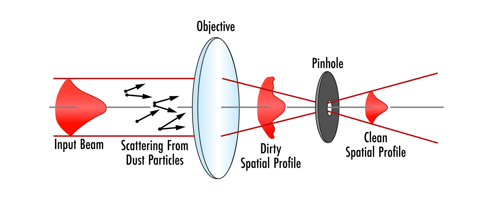
Figure 1: Basic layout of a spatial filter
The spatial filter assembly consists of a microscope objective, a pinhole aperture, and a positioning mechanism. This is comparable to the first lens of a Keplerian telescope design with the microscope objective serving as the first lens, and a positioning mechanism used to place the aperture at the point of focus. This setup is often paired with a collimating lens and used as a beam expander (Figure 2).
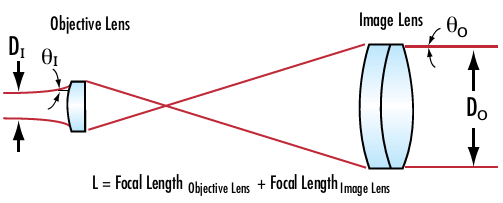
Figure 2:Keplerian beam expander design incorporating a spatial filter
The difficult part of constructing a spatial filter is deciding what size pinhole is sufficient to block enough light to clean the beam while staying above the point at which the laser beam starts to diffract. Equation 1 shows the percentage of power (p) transmitted through a spatial filter with a pinhole diameter of D, using a microscope objective with a focal length of f.
f = focal length of objective lens (mm)
w0 = laser beam waist (mm)
This equation can be used to find the optimal pinhole size for differing microscope objectives. A good rule of thumb is that approximately 99.3% of power is transmitted when:
The diameter found using Equation 2 is commonly accepted as the optimal size for a spatial filter. A problem often occurs, especially in more cost-sensitive applications, in which precision pinholes are not offered at the specific diameter determined using Equation 2. The solution for this is balancing the important aspects within the system application. By decreasing the pinhole size, you are almost always going to reach the diffraction limit, causing your beam to scatter in all directions and accomplishing the opposite of the spatial filter’s goal. However, when increasing the pinhole size, you are allowing more light to pass through, thus more stray light will negatively affect performance as well. In the majority of scenarios, increasing the pinhole size will be better for the system overall.
Spatial Filters at Edmund Optics
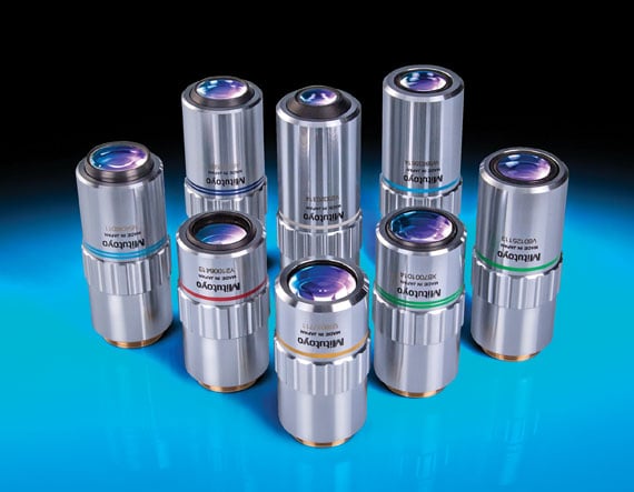
Microscope Objectives
- Tailored for Laser Applications
- Infinity-Corrected Objectives with Long Working Distances
- Reflective, Actively-Aligned Designs Available
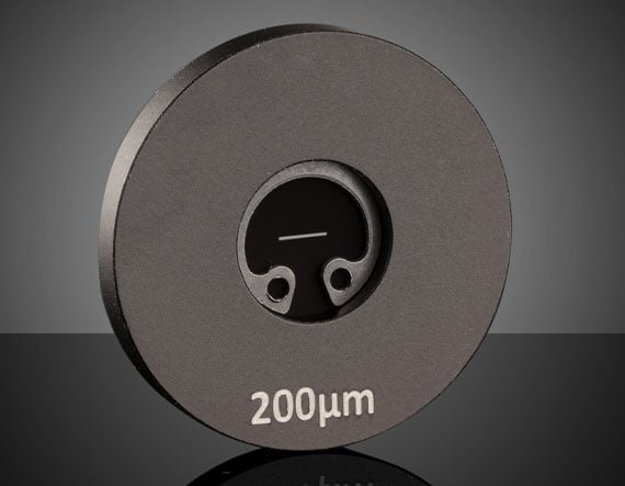
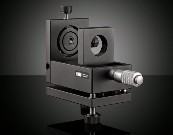
Pinholes and Slits
- Variety of Different Pinhole Sizes and Types
- Acktar Blackened Pinholes to Minimize Unwanted Stray Light
- High-Power Apertures Ideal for Spatial Filtering
Additional Resources
- Laser Beam Expanders
- Laser Beam Shaping Overview
- Gaussian Beam Propagation
- Beam Expander Testing
- Importance of Beam Diameter on Laser Damage Threshold
- Beam Expander Selection Guide


or view regional numbers
QUOTE TOOL
enter stock numbers to begin
Copyright 2023, Edmund Optics Inc., 101 East Gloucester Pike, Barrington, NJ 08007-1380 USA
California Consumer Privacy Acts (CCPA): Do Not Sell or Share My Personal Information
California Transparency in Supply Chains Act
This content may include material that has been generated or modified using artificial intelligence (AI).
The FUTURE Depends On Optics®